This thread has been locked.

If you have a related question, please click the "Ask a related question" button in the top right corner. The newly created question will be automatically linked to this question.

PGA305: PGA305

Part Number: PGA305

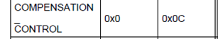
 I got my three PGA305 ICs not to set the COMPENSATION_CONTROL_REGISTER when using the I2C bus. I have One that Failed using the PGAxxxEVM-034 board then the other two that I'm driving with a micro-controller stop working as well just a day after. The PGA305 that failed on the EVM could be addresses using OWI then switching to I2C. My question are:

1.- What can make the I2C not to set the  COMPENSATION_CONTROL_REGISTER? 

2.- Is there a Way to fix this issue or do I need to replace the PGA305s?

3.- What I need to avoid doing to damaged them?

Please advice 

  • Part Number: PGA305

    Just adding what I had found: some how the  Digital Interface Control (M0 Address = 0x40000506) (DI Page Address = 0x2) (DI Page Offset =0x06) change from 0x42 to 0xF ,when this happen the I2C  don't write to the Compensation_control_ Register. I switched a few times using, OWI then switching to I2C, and the value changes and the I2C get disabled. The issue I have is what can I do on my design to overcome this issue as I just have I2C available?

    Please advice 

  • Hi Francisco,

    Do you have a schematic for your circuit that you can share? And some examples of the I2C commands that you are sending?

    Regards,
  • Scott
    The only difference with bellows drawing is that I2C_ADDR is grounded permanently.


    The commands I sent are just as the manual said they should be. The only think that change is that I added a routine to pull the PADC and TADC register to see how the signal was changing then they both quit after a day of testing, not continue just random testing time.
     
    I just kept    equal to 0x03 and I updated all 0x2 DI register updated at the beginning of the loop of continued pulling.
     
    I just did that to verify the analog part of the PGA.


    Francisco Requena
    DOWNHOLE TECHNOLOGY
    Mobile: +1 (432) 312-8647
    7414 Breen Dr, Houston TX 77086
     
  • Hi Scott
    Today I received a new set of PGA305s from Mouser and to avoid any confusion I used the PGA900EVM with the 305 GUI. I found these after setting all register and calibrating everything.
    • The bridge Voltage was always 2.5 Volts disregarding that I sat it to 1.2x.
    • I set all registers and proceed to calibrate the ADC & DAC changing the values of the bridge resistance. I got saved the calibration file and it is attached.
    • I switched the GUI to Compensation Mode and tried to read the Values of the COMBUF page. And I got all Zeroes as usual.
    • After that the I2C interface refused to engage and I got a message that I2C was disabled and needed to use the OWI. So I did then changed to I2C and verified that the eeprom value of DIG_IF_CTRL Register was changed from 0x42 to 0xCF  and the DAC_CTRL_STATUS Register was changed from 0x01 to 0x3C all of them in page 06 of eeprom.
     
    I don’t have documentation that explain what is going on with this DAC_CTRL_STATUS Register changes.
     
     
    The Maximum bridge differential input was 25 mV.
     
    I really need you support to get this device running…
    Please advice   
     
    Francisco Requena
    DOWNHOLE TECHNOLOGY
    Mobile: +1 (432) 312-8647
    7414 Breen Dr, Houston TX 77086
     
  • Scott,
    I repeated the test with the EEPROM_lock set to 1 and the Value was not changed but the result was the same. I managed to usw OWI to some how get to I2C the wrote 0x42 to the DI register of DIG_IF_CTRL Register  page 0x2 Offset 0x06 and it returns to normal.
    The issue I have is that  on my project board I can’t do that and I’m trying to find out what causes this odd behavior.
    Please Advice
     
    Francisco Requena
    DOWNHOLE TECHNOLOGY
    Mobile: +1 (432) 312-8647
    7414 Breen Dr, Houston TX 77086
     
  • Part Number: PGA305

    To who ever concern 

    I did figure the way to get the analog part , the  ADC and DAC running, but I still have few issues for which i need your help:

    1.- I cant get the COMBUF registers to provide any data, what  is needed  to get the COMBUF register working?   I cant get any data out of them the I2C.

    2.- I have few devices that are locked in compensation running mode, and I only have I2C built in to the circuitry, without space to implement OWI. I implemented the sequence also don't work in the GUI without success.

    what do i need to do to get these devices out of the Compensation mode using I2C?

    Any help is appreciated. 

  • Hi Francisco,

    "Just adding what I had found: some how the Digital Interface Control (M0 Address = 0x40000506) (DI Page Address = 0x2) (DI Page Offset =0x06) change from 0x42 to 0xF ,when this happen the I2C don't write to the Compensation_control_ Register. I switched a few times using, OWI then switching to I2C, and the value changes and the I2C get disabled. The issue I have is what can I do on my design to overcome this issue as I just have I2C available?"

    This register should not change in normal operation, and you should not be writing to it. As long as you don't write to this register, the I2C should function as normal unless the TI specific EEPROM space was changed. Do you have a dump of the EEPROM contents before and after this register change was discovered?


    "The bridge Voltage was always 2.5 Volts disregarding that I sat it to 1.2x."

    Where did you set the bridge voltage, and when did you measure it? If you set it using the Analog EEPROM page, you will need to power the PGA305 down and then restart it before the change will take place. If you set it in the Low Level Configuration page it will change immediately, but will not remain in the same state upon a restart.

    You mentioned that you set the EEPROM lock to 1. This will permanently lock the EEPROM so you cannot read or write to it. It is intended to protect your coefficients after you have completed calibration in a manufacturing environment before deploying the system to the field.
  • Hi Scott
    Thanks by your reply, I wish we could just have a brief talk to clarify few issues.
    I managed to find out the missing registers that makes the PGA305 works fine in DI ON and  Compensation in Reset. I also managed to find the reason why the devices where locked on Compensation Mode and developed a routine to take them out of that mode based on the routine the PGA305 EVM software.
    The only issue I have now is  when I place device in Compensation Mode (COMPENSATION_CONTROL Register = 0x00) and try to read the COMBUF register, the readings are just Zeroes and the device get stuck on that mode. This is the protocol I’m using to read the COMBUF registers:
    • With COMPENSATION_CONTROL Register = 0x03:
      • Update DI registers (Page 0x2 Offset = Various)  that have  EEPROM backup values.
      • Set DI registers (Page 0x2 Offset = Various)  that has not EEPROM backup Values. Example: PADC_CONFIG (DI page address = 0x2) (DI page offset = 0x23) I don’t Have EEPROM Address for this one but I found this one was the reason I didn’t get the 24 bits correctly set.
    • Set the   COMPENSATION_CONTROL Register = 0x00
    • Loop:
      • Read PADC:
        • Write 0x00 to COM_DIF_TO_MCU_B1 (DI page address = 0x0) (DI page offset =0x08): just to clear register as I don’t know what effect it may have.
        • Write 0x00 to COM_DIF_TO_MCU_B2 (DI page address = 0x0) (DI page offset =0x09) : as per PGA305 instructions,
        • Write 0x01 to COM_RX_STATUS (DI page address = 0x0) (DI page offset = 0x0A): I found that doing this the PGA305 reads the COM_DIF_TO_MCU registers , I did bypassed this step with same results.
        • Read COM_TX_STATUS  (DI page address = 0x0) (DI page offset = 0x06): but the PGA305 never return any value.
        • Read COM_MCU_TO_DIF_B1 (DI page address = 0x0) (DI page offset =0x04) : as per PGA305 instructions
        • Write 0x70 to COM_DIF_TO_MCU_B2 (DI page address = 0x0) (DI page offset =0x09) : as per PGA305 instructions
        • Write 0x01 to COM_RX_STATUS (DI page address = 0x0) (DI page offset = 0x0A): I found that doing this the PGA305 reads the COM_DIF_TO_MCU registers, I did bypassed this step with same results.
        • Read COM_TX_STATUS  (DI page address = 0x0) (DI page offset = 0x06): but the PGA305 never return any value.
        • Read COM_MCU_TO_DIF_B1 (DI page address = 0x0) (DI page offset =0x04) : as per PGA305 instructions
        • Read COM_MCU_TO_DIF_B2 (DI page address = 0x0) (DI page offset =0x05) : as per PGA305 instructions
        • I convert the 24 bits to 32 bits but all is Zeroes before that happened.
     
     
    I do the same with TADC but results are the same.
     
    I found that the watchdog get set, even when the it is disable on  WDOG_CTRL_STAT (DI page address = 0x2) (DI page offset =0x1C).
     

    What is the correct protocol to read the COMBUF using I2C and what are the timing requirements?


    Please advice


      •  
     
    Francisco Requena
    DOWNHOLE TECHNOLOGY
    Mobile: +1 (432) 312-8647
    7414 Breen Dr, Houston TX 77086