This thread has been locked.

If you have a related question, please click the "Ask a related question" button in the top right corner. The newly created question will be automatically linked to this question.

LMT01: Interfacing LMT01 with MSP430

Part Number: LMT01
Other Parts Discussed in Thread: MSP430FR5994

Hello there,

I am trying to use LMT01 with my project that has an MSP430FR5994 MCU.

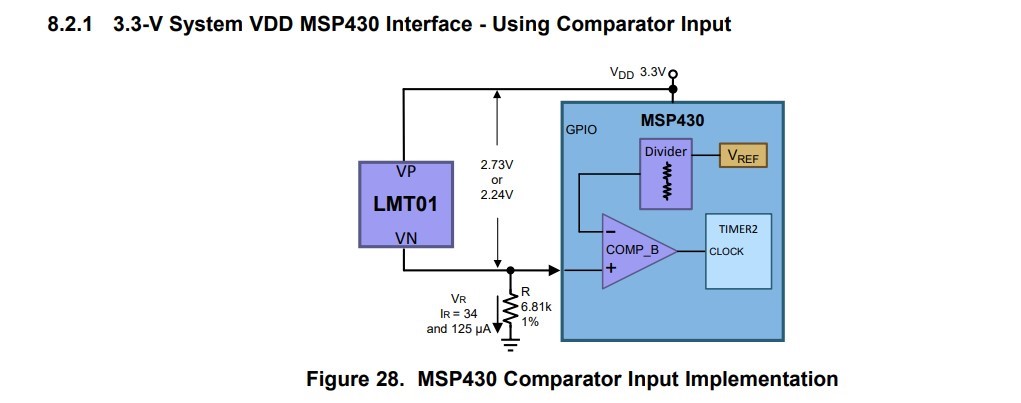
I am trying to use the hardware peripherals as much as possible and trying to implement the circuit diagram in LMT01 datasheet Figure 28.

I want to implement the same circuit in Figure 28.

1. Connect the LMT01 output to comparator of the MSP430

2. Connect MSP430 comparator INTERNALLY to the TIMER clock input as shown in the figure.

3. By doing 2, I will avoid using an interrupt for every pulse, and an extra physical pin.

And so the question is: How can I connect the comparator output INTERNALLY to the TIMER CLOCK INPUT.

An possibly a related question is: 

The clock for the timer can be as stated in the datasheet  TAxCLK, ACLK, SMCLK and INCLK. What is INCLK? Where does INCLK come from?

Kind Regards

Kerem Oktem

  • Hi Kerem,

    Only one pin on the MSP430 is needed to count pulses from the LMT01. However, it is easier and more reliable software-wise to use a GPIO to power the LMT01. This allows you to synchronize the set of pulses to a capture window by powering on, counting for LMT01 max transmit time, then powering off the LMT01. If you don't do this, you'll need to write an algorithm that resets the count at the appropriate time based on time since last count activity.

    I'm redirecting your post to the MSP430 team so they can answer your other questions.

    Thanks,
    Ren
  • Hi Ren,

    Thank you very much for your kind answer. My question is related to how to count the pulses not with software but with hardware resources only.

    Thank you for your interest

    Kind Regards

    Kerem