


Hi there,
with the following set-up (signal generator VG1 supplies 3.3V square wave)

we get the following output. The first diagram looks as expected...

But looking at the position of power-up, we get this:
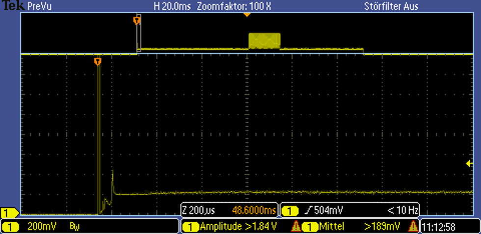
There is an extra pulse that can not be found in the data sheet. There is also a second, smaller pulse, which sometimes makes it through the comparator in the actual application circuit. In turn, this causes trouble in the application software. Is this to be expected? Are we dealing with faulty sensor elements? Are there any recommendations to ignore initial pulses over a specific time?
Initially, we suspected a problem with out circuit, so we took these measurements with just a signal generator and resistor. The diagrams here are the result.


