This thread has been locked.

If you have a related question, please click the "Ask a related question" button in the top right corner. The newly created question will be automatically linked to this question.

TPS8804: Concerning the SLC interface in TPS8804 smoke detector AFE

Part Number: TPS8804

Hi there!

We are currently evaluating the awesome TPS8804 smoke detector AFE.

And I noticed that there is a SLC interface which looks really handy, and offers a power-line-communication-like interface.

We've noticed that SLC seems to be a well adopted physical layer in the fire alarm industry, but without a unified standard. (and often time closed protocol)

We would like a develop a home automation & fire security system using this SLC interface.

Wondering if there is a SLC reference design or guideline.

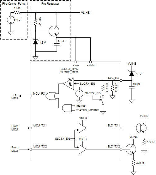
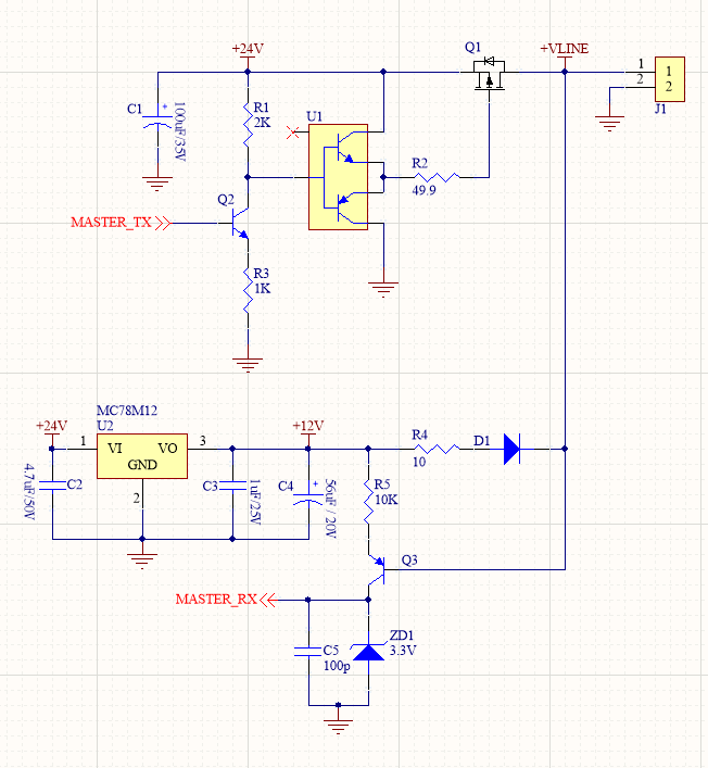
Especially the hardware implementation of master side of the power bus, that is, the one who talks to TPS8804 and other SLC slaves.

Here is a screen shot from TPS8804 datasheet.


Thank you all in advanced!

Zt.


  • Hi ZT,

    I have notified our expert regarding this topic. Please expect a response by 4/23/20.

    Thanks,

    Costin

  • Hi Zt,

    Thanks for your interest. I can support questions you have on the TPS8804 device. I will reach out to the fire safety systems team regarding a complete SLC reference design or design guideline. I will have a response to you by 4/21/20.

    Best regards,

    Grant

  • Thank you so much, Grant and Costin. :)

    I will be waiting for your further replies.

    Zt.

  • Hi Zt.,

    Thanks for your patience. Here is the response from the TI fire safety systems team:

    "We don’t have SLC reference designs because each manufacturer has their own protocol.  This is intentional as the commercial detectors are mandated to be certified to only work with a particular fire panel or set of fire panels.  Because of this liability, the panel manufacturers keep the protocol and implementation proprietary so that they can guarantee that only the detectors and appliances they have control over can operate with their panel.

    Based on the above, if this customer is developing their own fire security system then the protocol and panel hardware implementation is entirely up to them.  The guidance we can provide is that a large majority of panels use voltage modulation for communication from the panel to the devices and current modulation for communication from the device to the panel.  All communication is initiated by the panel except for Alarm or Trouble conditions.  Also, the supplies on the detectors connected to the SLC needs to be diode blocked and current limited.  The current limit placement varies depending on the implementation, but needs to be before the switches used for communication and alarm."

    Because many designs use voltage modulation for communication, we've selected our TPS8804 typical application to sense voltage on the SLC line and drive the line with a constant current or voltage. The schematic and waveforms below demonstrate the sensing and driving. Other hardware may be necessary to meet the SLC requirements; please refer to UL268 and UL864 standards.

    We also have a fire alarm control panel page that may help with your system design.

    http://www.ti.com/solution/fire-alarm-control-panel-facp?variantid=34402&subsystemid=28900

    Let me know if you have any other questions.

    Best regards,

    Grant 

  • Hi, Grant!

    Thank you so much for your precious reply.

    Especially for pointing me to the UL268 and UL864 standards.

    That does help me a lot.

    I made a tentative schematic today. Could you please take a look?

    Most component values are still to be determined. However, the circuit captures the idea that:

    1. Master transmits signals through voltage modulation by tuning off Q1,

    2. Senses the current modulation(while Q1 if off) from slaves through R4, D1, (similar to your 1K resistor in your diagram)

        and tuning on Q3 accordingly.

    Have some thoughts? i am all ears. 

    Best regards,

    Zt.

  • Hi Zt,

    No problem. Here are my thoughts on your schematic:

    1. There's nothing pulling down +VLINE when MASTER_TX is low. I recommend using something to pull-down the line to improve the signal's resilience to leakage and noise.
    2. There's nothing pulling down MASTER_RX when VLINE is high. A pull-down is needed to reset the voltage.
    3. Using R4, D1, R5, and Q3 for current detection may need precise fine-tuning. I recommend using an architecture resilient to diode and transistor parameters, which have large variances from part-part and across temperature.

    I'm not an expert on SLC and the associated standards, so please take my advice only as a suggestion.

    Best regards,

    Grant

  • Thanks, Grant!

    Really appreciate your effort.

    I will work more based on your advice.

    Best regards,

    Zt.