


Other Parts Discussed in Thread: SYSCONFIG, CC2640R2F, CC2640, CC2650
Hello sensors forum,
I'm facing some difficulty in getting the LMT84 temp. sensor to work properly with MSP432P4011 running TI-RTOS, with peripherals configured through sysconfig. I have asked a related question in the MSP forum but it hasnt been resolved so posting it in the sensors forum too.
My previous post - 
A summary - I have a custom PCB with LMT84 connected to the MSP432 ADC pin (P5.4/ADC14.A1). I'm using internal VDD (+3.3V) reference to do a single ended measurement. I have configured the ADC using sysconfig tool, which does not allow me to control the sample/hold time etc.
My circuit schematic is as below -
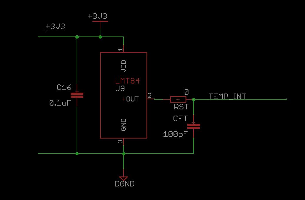
My issue -
The LMT 84 is outputting a steady 888 to 910 mV output (measured using DMM) corresponding to the correct room temperature found by (1035 - Vout) / 5.5. But my MSP432 ADC reads the same very inconsistently. I get readings all over the place including up to 1000 mV. The average reading is about 50-60 mV higher which completely throws off the temperature reading. This is repeatable across multiple identical PCBs we have manufactured (machine assembled).
I understand that there are some considerations about the RST resistor I have set to 0 ohms in the above schematic. The LMT84 datasheet recommends a 3k resistor if the loading capacitance is more than 1100 pF. However I looked at the MSP432 ADC spec and it seems that the loading capacitance on the ADC is < 15 pF (Table 5.27 on page 70 of MSP432P4011 datasheet), which means my total loading is < 1100 pF. My understanding is that I should not be needing RST to be 3k.
However I did try with RST = 3k and got somewhat better results, but not quite to what I was expecting. There is still a large offset and some variance in the measurements.
We have used the same circuit with a CC2640R2F which has a similar SAR ADC. In that design, I was able to configure the ADC's sample and hold time (this was before sysconfig) and that worked reasonably well.
Is there some obvious flaw in the approach we are taking? The multimeter measurements match well, it's just an issue with the ADC being able to read those accurately.
Would appreciate some insight on this!
-Shreyas


