This thread has been locked.

If you have a related question, please click the "Ask a related question" button in the top right corner. The newly created question will be automatically linked to this question.

DCA1000EVM: Error using DCA1000EVM CLI Software

Part Number: DCA1000EVM

I am trying to extract raw data from the DCA1000 with an AWR 1642BOOST in Ubuntu, however, I am getting an error and it is not working. Once I have typed ./DCA1000EVM_CLI_Control record configFile.json and then ./DCA1000EVM_CLI_Control start_record configFile.json the LVDS PATH ERR LED comes on on the DCA board and nothing happens until I type in ./DCA1000EVM_CLI_Control stop_record configFile.json and I get the following error: 

Stop Record Command: Timeout Error! Couldnt read the record process status. [error -4068] 

I'm not sure whats going on. I was wondering if anyone can help.

Cheers,

Charlie

  • Did you issue ./DCA1000EVM_CLI_Control fpga configFile.json before start_record?

  • Hello again Sabeeh!

    Yes I did, sorry I forgot to mention it

    Charlie

  • The LVDS_PATH_ERR_LED indicates NO LVDS DATA received from the radar EVM within a timeout period.

    Some debug steps:

    1. Ensure that switch 2.5 on the DCA1000 is set to CONFIG_SW. 
    2. Power switch on DCA is correct.
    3. Host IP address is set to 192.168.33.30
    4. json file matches that described in SDK user's guide.
    5. Radar is flashed with latest out of box demo. 
    6. Radar is being sent a valid cfg file that has the lvdsStreamCfg with parameters -1 1 1 1, typically by means of mmWave Demo Visualizer. 

    Error codes are described in the DCA1000 user's guide: https://www.ti.com/lit/ug/spruij4a/spruij4a.pdf

    Please read closely all available documentation.  

  • 1-5 were already correct. I just tried updating the lvds configuration you suggested, but still had the same error. Is there anything else that could be wrong? What should the SOP jumpers on the radar be set to?

    Thank you for your help,

    Charlie

  • SOP0 and SOP1 should be ON, and SOP2 should be off. 

    Is the power supply 5V and atleast 2.5A?

  • That's what it was before. Yeah it is. Would it make a difference flashing the radar device on a different PC? I have been using my Windows PC for the demo visualizer but using a linux PC with the CLI. Would it be better to use the demo visualizer on the linux PC? Or is there anything else that could be wrong?

    Charlie

  • We need to understand if the problem is radar or dca. When you send the cli, does the sensor respond with done? Are you sure there are no errors? Could you probe the lvds signals to make sure they are there?

    Are you starting the data record first or starting the sensor first?

    Is the radar mounted well to the DCA?

    I’m no longer aware on how to solve your problem. Recall that this is not the intended use of the dca.

  • No it doesn't respond with anything. No errors come up in the terminal and if I run query_status before stop_record it says Record process is initiated [Status -4031].

    What do you mean by starting the sensor?

    I have been running:

    ./DCA1000EVM_CLI_Control fpga configFile.json

    ./DCA1000EVM_CLI_Control record configFile.json

    ./DCA1000EVM_CLI_Control start_record configFile.json

    Then wait for a bit and then

    ./DCA1000EVM_CLI_Control stop_record configFile.json

    Is there anything extra I need to do?

    The sensor is bolted to the DCA1000 and there are no visible issues with the 60 pin samtech connector.

    I just tried it in mmwave studio (on a different PC) again and it worked fine first time.

    I understand it may not be possible. It is really kind of you to be so helpful though.

    Thank you,

    Charlie

  • Hi Sabeeh,

    I hope you had a good weekend. I have written a script using pyserial to load the .cfg file onto the sensor and control the sensorStart and sensorStop functions. This seems to be working, however, I am still getting the same issue and the LVDS_path_ error LED is still coming on. I can't find much information about it in the various user guides, but do you need to change any settings in the cfg file, for example, to make the sensor output its data over the samtech ribbon rather than via its usb? I've noticed that the mmwave studio sends a BSS.bin and MSS.bin file to the radar, but I have not seen any suggestion that this is necessary to do with the CLI software. Do I need to send the radar binary files?

    Thank you for your help,

    Charlie

  • Hi Charles,

    There is no relation between USB and LVDS. Raw adc data does not come from the USB port. In your python script, do you read back any commands from the sensor? The sensor should be replying with done. If you believe it to be working, are you getting point cloud data on the second serial port? 

    What mmwave studio does is not completely related to how the DCA1000 CLI works, so there is no need of sending binaries. However, I will strongly recommend that you try using mmwave studio on windows just to ensure that you are able to even capture data from the sensor. This will confirm there are no other issues. You can find a training video here:

    https://training.ti.com/dca1000-training-video

    If you have issues using mmwave studio, please create a new thread. 

  • Hi Sabeeh,

    I have already tried it with the mmWavse Studio and it works. My serials script gives outputs saying done etc. from the UART port and a point cloud output from the data port, but it does not seem to work when the 60 pin ribbon cable is connected. Any idea why this is?

    If I plug the ribbon cable in after is it running the DCA board flashes the data_tran_prg, but the same error still occurs if I do it at the same time as the CLI software.

    Thank you for helping me.

    Charlie

  • Hi Charlie,

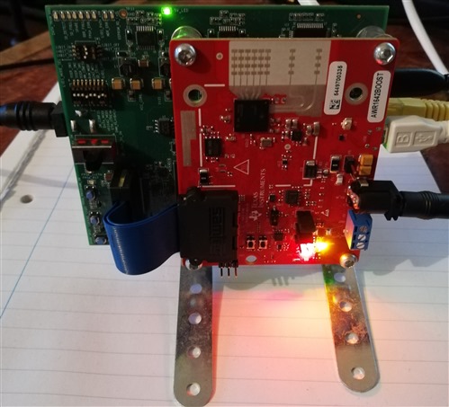
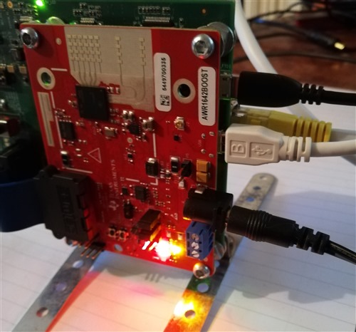
    Could you please post an image of your setup? Does it match what is shown in the training video I linked?

  • Here is the physical setup. Both boards have a 5v power supply (AWR=3A and DCA1000 =2A). The DCA board has an ethernet cable and USB in RADAR_FTDI port. The sensor has a USB cable in the only USB port. Jumpers are on SOPs 0 and 1.

    Thank you,

    Charlie 


  • I currently don't have a 1642 on hand to test this out for myself. Please give me many days to get access to one and I can test this then. 

  • That would be really great. Thank you

    Charlie

  • Hi Sabeeh,

    I thought I thought I would let you know that I have made some progress. I have removed the jumper on SOP1 and switch SW2.3 to AR1642_MODE. The lights on the DCA board now flash as they should and I can see the packets coming in with wireshark. I still ge tthe same error when I use the stop_record function and it is not storing the raw data in a file. However, I can write a python script to use the packets from the ethernet, which will allow me to use the data in real-time as I originally desired.

    Thank you so much for your help,

    Charlie