This thread has been locked.

If you have a related question, please click the "Ask a related question" button in the top right corner. The newly created question will be automatically linked to this question.

AWR1642: mmWave doppler range

Part Number: AWR1642
Other Parts Discussed in Thread: DCA1000EVM

Hi Team,

Good day. Kindly assist our customer's inquiry below:

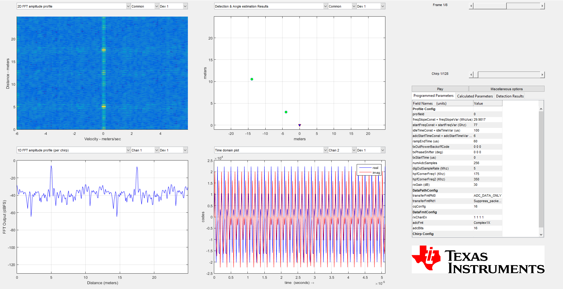
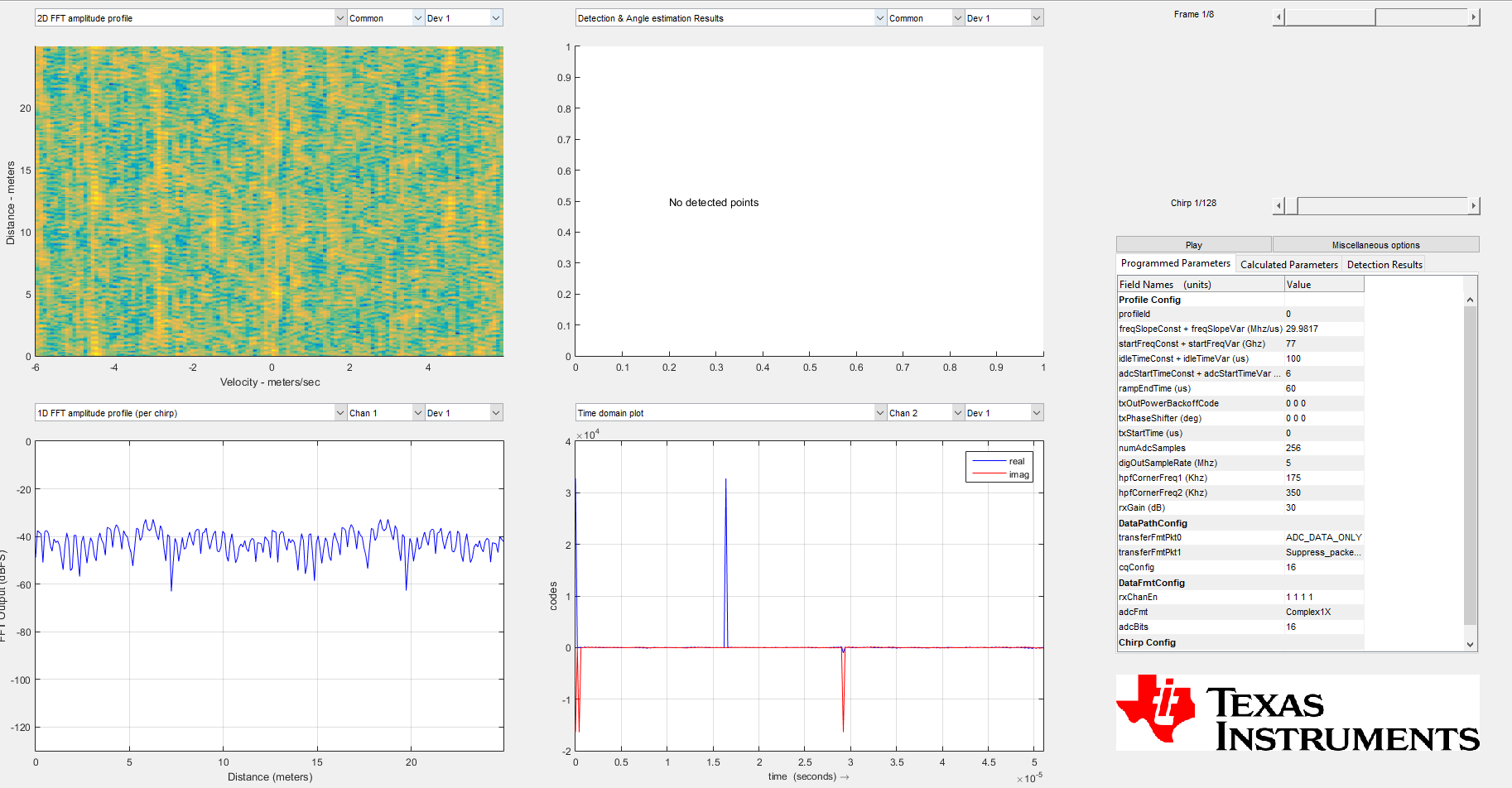
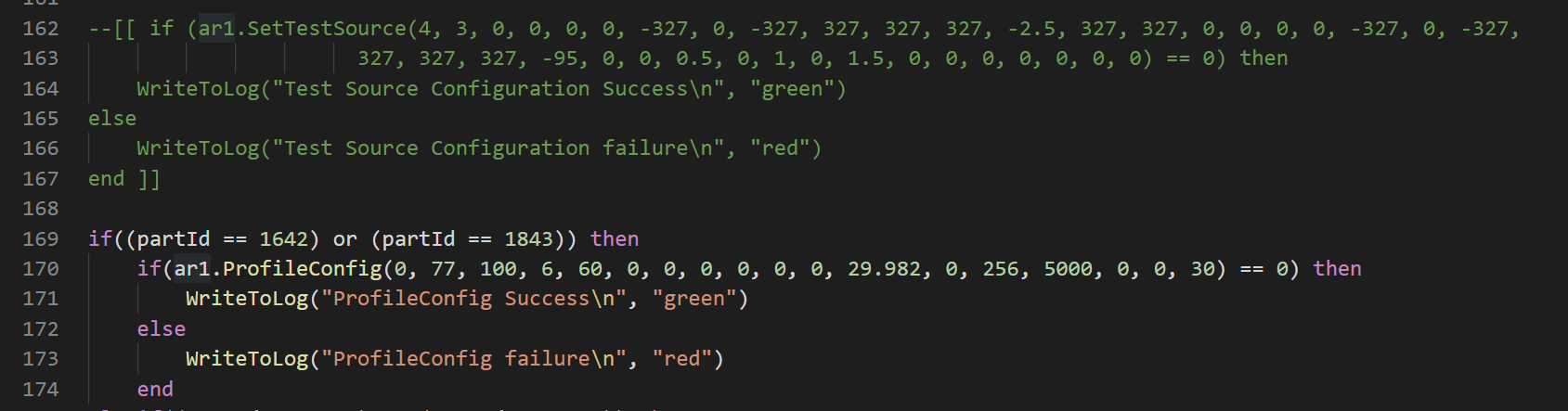
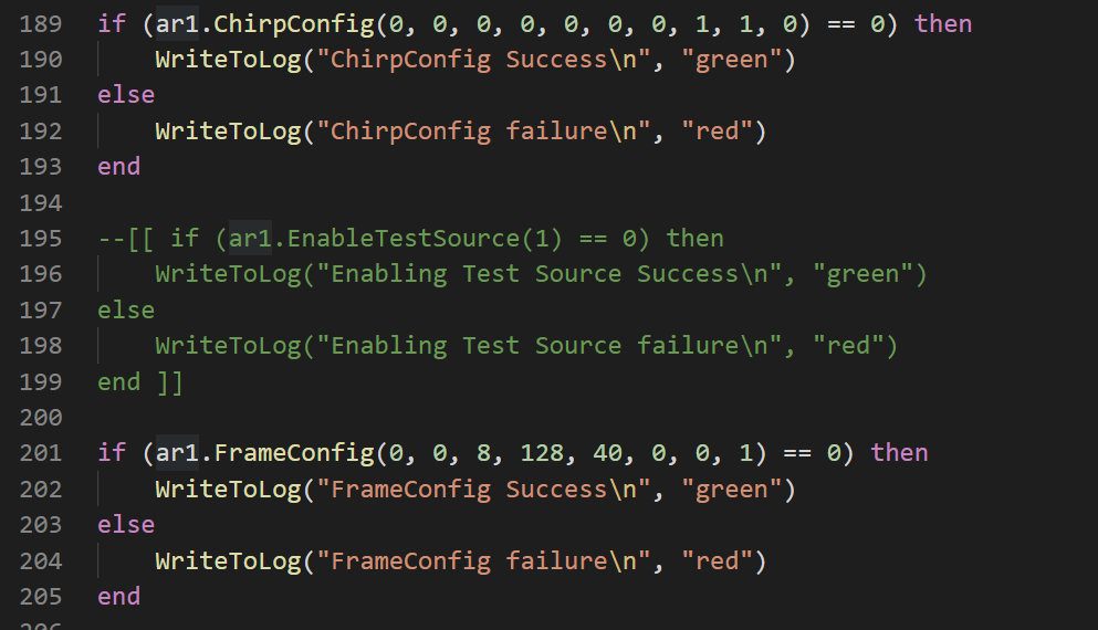
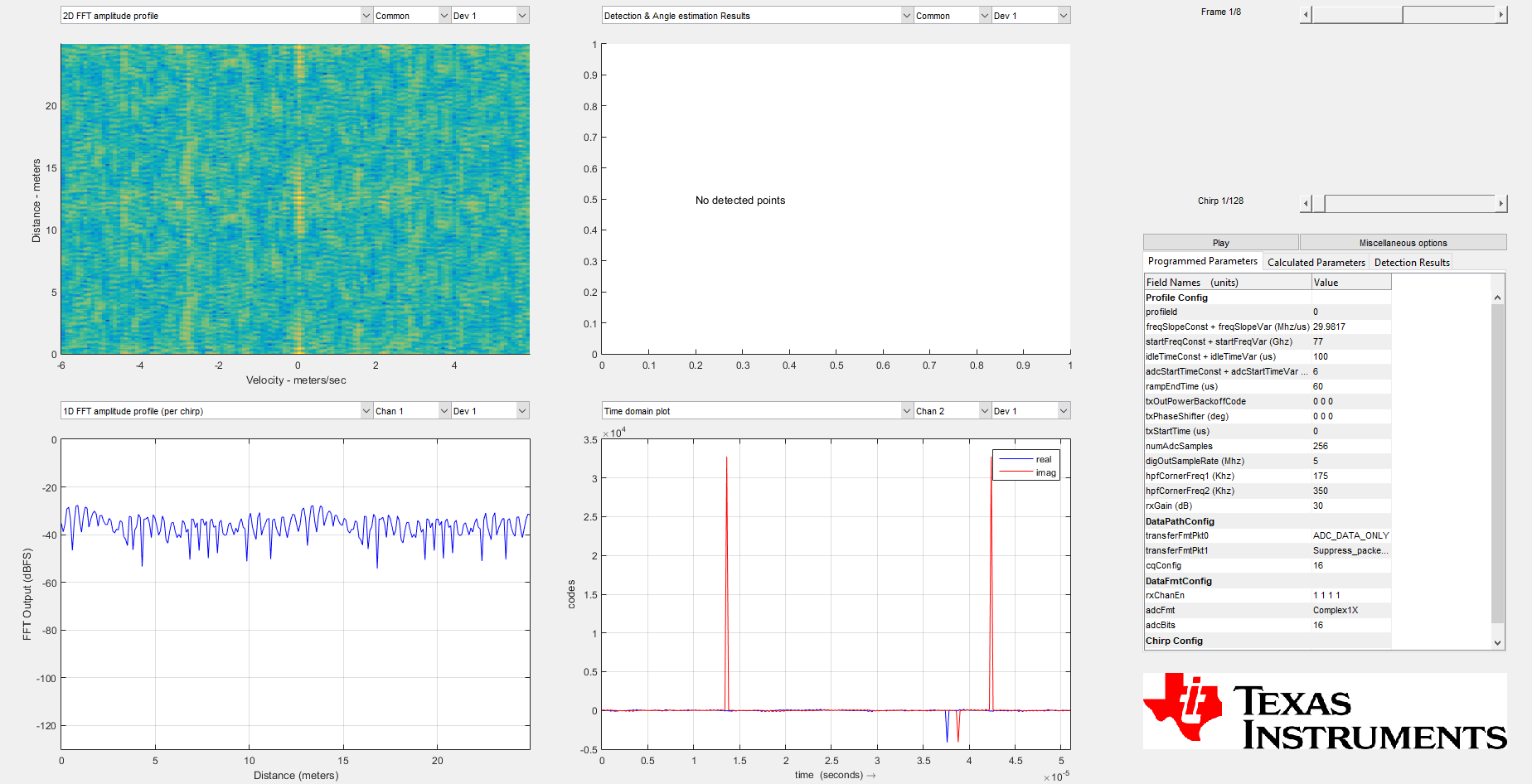
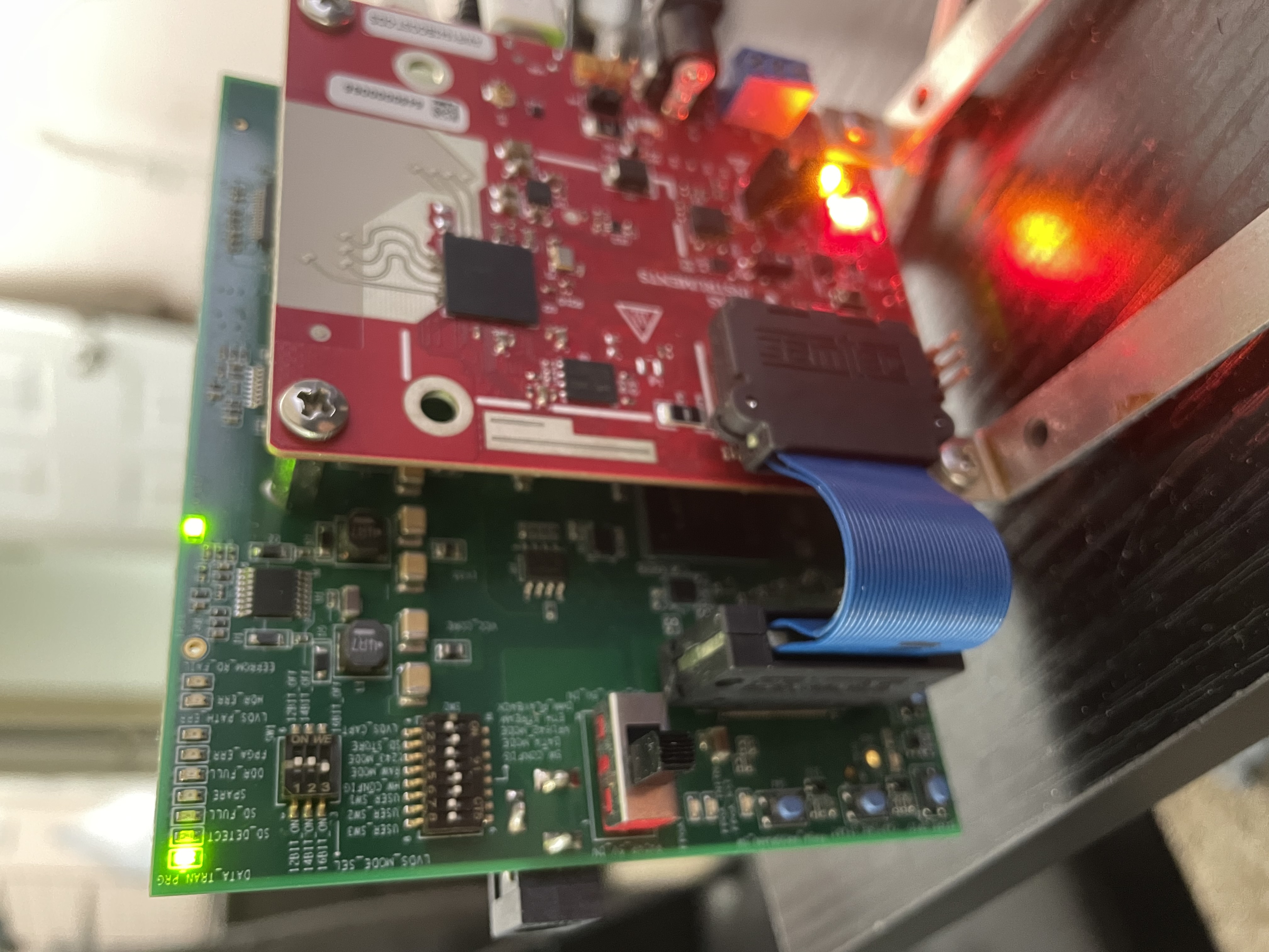
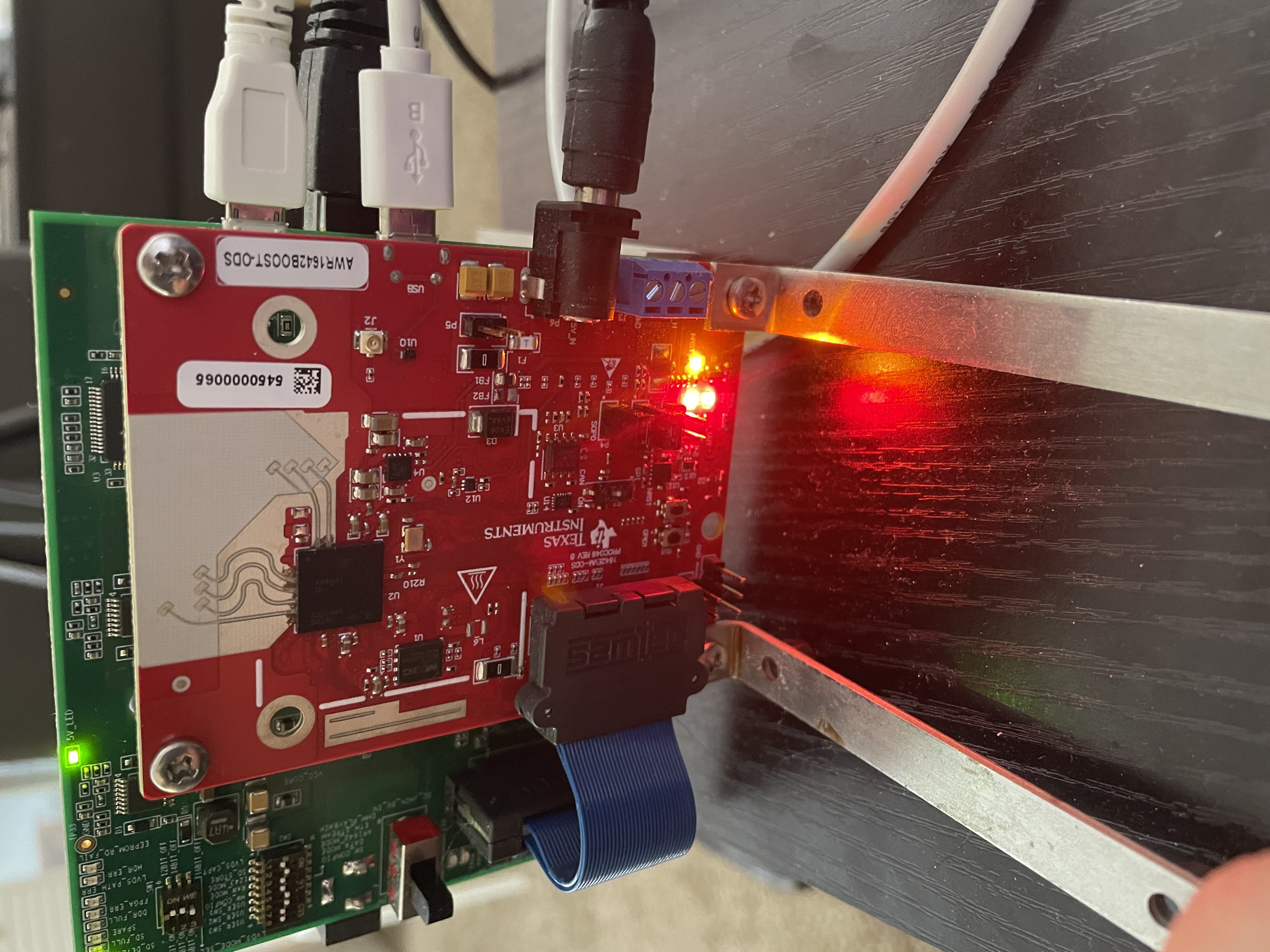
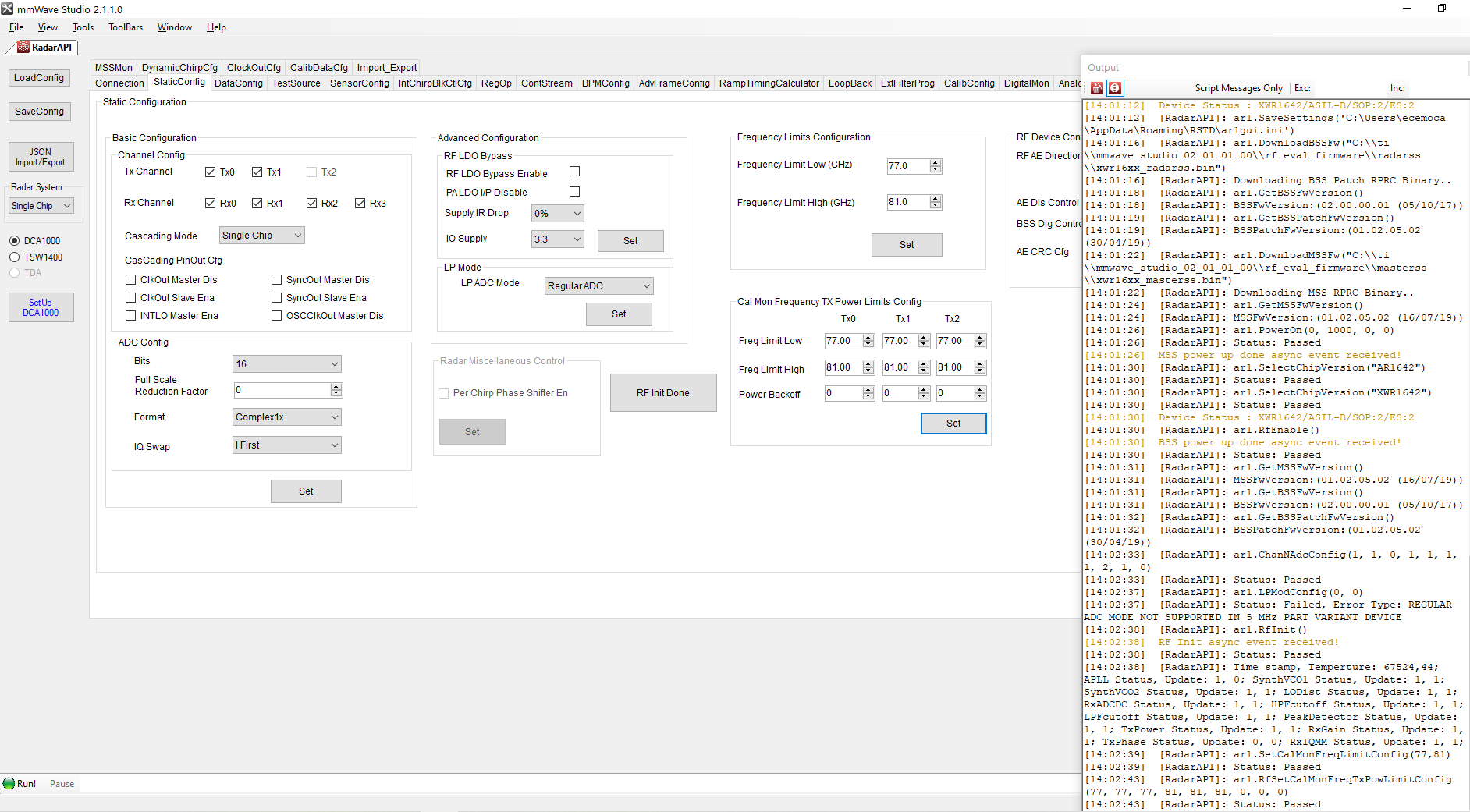
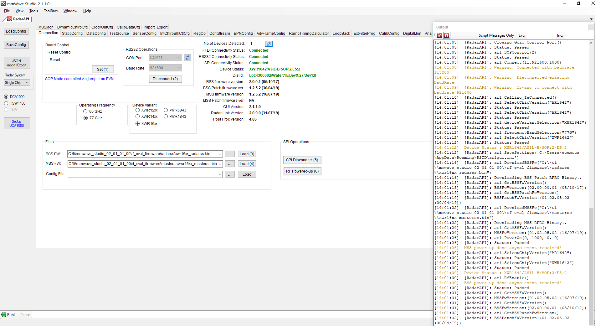
I have question related to my mmwave awr1642. I can't get correct range doppler figure using awr1642 and dca1000 with mmwave studio. I follow the extra steps in the DCA1000 Training Video on training.ti.com/dca1000-training-video, but still got the strange range doppler for awr1642 but the 1642 board can get correct range doppler through demo visualizer using the firmware in the sdk.

We are looking forward to your response and thank you for the usual support. Have a great day.

Best regards,

Jonathan

  • Hi,

    First, are you able to capture raw data correctly?

    I think it would be helpful to first place a corner reflector at 1-3m in front

    of the sensor and make sure you are able to

                 1) capture the raw data

                 2) post process the raw data

                 3) see a peak in the range FFT

    Thank you

    cesar

  • Hi, Cesar. Thanks for your reply.

    I sit in front of the radar at about 1m. And I can get correct range doppler/range FFT using the mmwave studio for iwr 1443 board, and I use the exact same setting for 1642 (expect the two firmware files and the LVDS lane number). I can also get correct range doppler using the demo visualizer using 1642. But I can't get correct range doppler with 1642 on mmwave studio either using the mmwave studio directly for plotting or use the matlab parser script from TI for raw data and then plot it (Both of them work for iwr 1443 board and the matlab parser script will notice the tiny raw data format difference for 2 lane and 4 lane data). 

    Looking forward to your response and thank you for the usual support. Have a great day.

    Best,

    Xi Cheng

  • Xi,

    You can try using the capture demo LUA script in mmWave Studio. It is located in this directory:

    C:\ti\mmwave_studio_02_01_01_00\mmWaveStudio\Scripts

    You can use the DataCaptureDemo_xWR.lua script and see how this output looks in the PostProc tool.

    Regards,
    Kyle

  • Hi, Kyle, thanks for your reply.

    I tried using the DataCaptureDemo_xWR.lua script. It works well and can generate a reasonable correct result as shown below. And I find the main difference between the demo and my setting is the firmware and the testsource. Does it mean the problem come from the firmware in C:\ti\mmwave_studio_02_01_01_00\rf_eval_firmware

    Best,

    Xi Cheng

  • Xi,

    If you attempted to upload an image in your most recent post, you will need to upload it again.

    If you are sitting in front of the radar, then you should not be using the testsource. This will interfere with your results if people and other objects are placed in front of the sensor.

    Regards,
    Kyle

  • Hi, Kyle, thanks for your reply.

    I try to disable the testsource, and I found that the results become error once the testsource is disabled, even with the DataCaptureDemo_xWR.lua script.

    Running the DataCaptureDemo_xWR.lua script (the testsource is enabled as default)

    After running DataCaptureDemo_xWR.lua script, disable the testsource and run the data collection again. (I was sitting in front of the board)

    So it still can't capture the user in front of them. 

    Best,

    Xi Cheng

  • Xi,

    I would recommend removing the ar1.EnableTestSource(1) command from the capture demo script. Please make sure the script does have any Test Source references.

    Please also make sure the LP mode is set to the Low Power ADC. This is the only supported option on AWR1642.

    Feel free to upload a few images of your physical setup to assist in your debug.

    Regards,

    Kyle

  • Hi, Kyle, thanks for your reply.

    I tried commenting out the command related to test source setting in DataCaptureDemo.lua.

    all the other part of the script is not changed. The LP mode is set to Low Power ADC mode by the script. And the data collected is still incorrect.

    And here are the physical set up of my device

    Best,

    Xi Cheng

  • Xi,

    So are you getting correct results from the DCA1000EVM when the test source is enabled but the incorrect results when the test source is disabled?

    I wanted to make sure that I understand the current situation.

    When the test source is enabled, is the sensor able to detect you sitting in front of it?

    Regards,
    Kyle

  • Hi, Kyle, thanks for your reply.

    Yes, I can only observe correct range doppler when the test source is enabled. And I tried moving my body back and forth in front of the radar with test source enabled but I can't see dots with non zero velocity in the range doppler. So I don't think the sensor is able to detect me.

    Best,

    Xi Cheng