This thread has been locked.

If you have a related question, please click the "Ask a related question" button in the top right corner. The newly created question will be automatically linked to this question.

HDC2080: HDC2080 - Misbehaviour - Humidity read as 100%

Part Number: HDC2080

Hello,
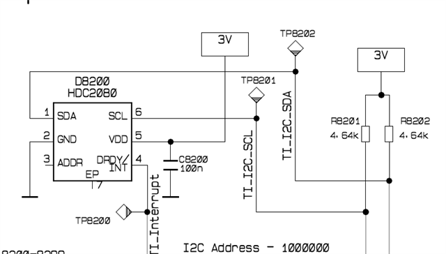
We are using HDC2080 sensor in one of our design and we have observed misbehaviour of the sensor. The sensor reads 100% humidity continuously and recovers only after a power reset. And this is observed soon after power on of the device and also during mid of testing.

Below are other details.

1) The actual humidity was around 16%, where as the sensor read 100%

2) Also temperature offset of 2-3 degrees observed.(Temperature reading was 2 degrees higher than expected)

3)After the power reset of the board,the sensor started reading the optimum value of humidity and temperature.

4) This was observed in 2 of our products. One was kept in temperature chamber at 40 degrees and one was in room temperature

During this phase of misbehaviour we have conducted a few experiments and captured few observations. The details are explained below
1) Kept the PCB in most ventilated place.
2) Place the finger on the sensor for some time
3) Blew hot air on the sensor area. After this process only temperature reading showed higher value but the humidity was still 100%
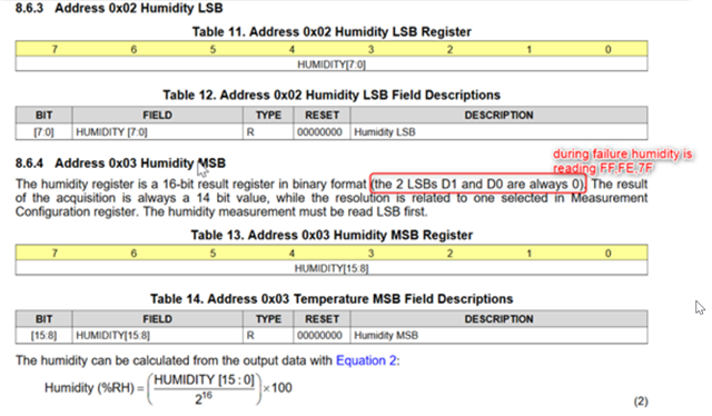
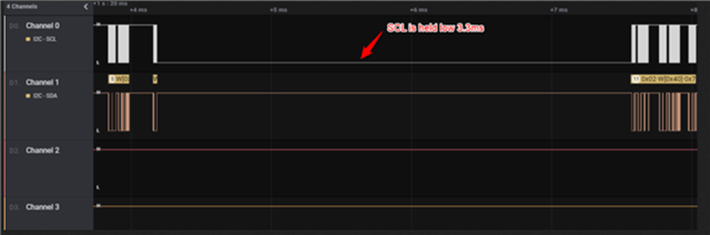
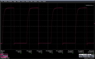
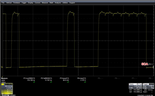
4) We are using I2C as communication interface, so we analysed the communication data as well. We see that,according to data sheet, the values in the 2 LSBs D0 and D1 needs to be 0 in humidity register.This is not met
5) Finally we did a power reset, the sensor started working normally.

All the necessary pictures have been shared as attachment

Please let us know if you need any other information. Can somebody help us solve the issue at soonest as we are moving to C sample design with this sensor already.

  • Dear Surabhi - 

    Welcome to the E2E Forum and thanks for posting! 

    Regarding the SCL being held low, what else is in your system? The HDC2080 does not support clock stretching, so something else is holding the line low. Both the SCL and SDA lines should be high after sending the start conversion. 

    Thanks for the screen captures - they are helpful!

    You can check out this FAQ on the topic of the values returned: 

    https://e2e.ti.com/support/sensors/f/sensors-forum/878721/faq-hdc2080-hdc2010---i-am-getting-incorrect-values-for-example--40c-or-0-rh-or-both-from-hdc-device-for-my-first-read-or-for-any-read-how-to-troubleshoot-the-problem?tisearch=e2e-sitesearch&keymatch=HDC2080# 

    Here, if you could show the start conversion command being sent (a write of 0x01 to 0x0F) , with the delay between it and the read of 0x00 through 0x03, that would be helpful. You could also read out all four bytes at once instead of breaking it up as you are doing. Also, you can read 0x04 register (for 0x80) and use the DRDY/INT pin to indicate when data is ready. 

    lastly, for troubleshooting purposes, at power up, you can read register 0x0F and make sure it is 0x00 before starting normal operations.  

  • Hi Josh,

    Thank you for your reply. As the sensor is in Auto measurement mode, the communication starts as it is mentioned in the above image.

    With respect to DRDY/INT, we are using polling technique in the software.

    With respect to reading register at power up, we will try this during debug. Is there anything else you would like to recommend for further analysis?

  • Dear Surabhi - 

    the troubleshooting steps etc. listed above are what I can recommend at this time, to start with. 

  • Dear Josh,

    We have conducted the experiments as mentioned but we see no valid results

    https://e2e.ti.com/support/sensors/f/sensors-forum/951961/hdc2080-hdc2080-invalid-results

    The link below also has similar issue discussed. Can you please suggest any other solutions or bug fix method?It will be of great help

  • Dear Surabhi - 

    As indicated previously, with no solid information available from your system, we cannot guess as to what might be your firmware or hardware issue. If you can share your captures directly for review, that would be most helpful to get to a resolution for you quickly. 

    I can also share with you here a link to the Silicon Users Guide in which you can see the flow charts for the operation of the device and compare to your captures locally and should point us in a direction here.  

    https://www.ti.com/lit/pdf/snau250

  • Dear Josh,

    Here i am writing in details about the questions

    1) We are running in auto mode with frequency of 1Hz. So no data ready command is used

    2) Time taken for a write of 0x01 to 0x0F to next read is 2.1sec.

    3) The read pattern with break between humidity and temperature is a choice made by software team.

    4) The reset value of 0x0F is 0. Is there any reason why it will be different than that soon after power up?

    5) We also saw similar issue here in the below discussion. This is exactly the same problem we are facing. Can you please have a look once?

    https://e2e.ti.com/support/sensors/f/sensors-forum/951961/hdc2080-hdc2080-invalid-results

    6)Below i have also attached SCL and SDA signal details

  • Dear Surabhi - 

    if you have set the device for 1Hz reads, then logically you should read out at 1Hz, correct? When using the auto measurement mode, for best practice, whether using the DRDY/INT pin or not; you do still want to read the 0x04 register for 0x80 before reading for measurement values, then read registers 0x00 through 0x03 out all at once. 

    Since you are using a custom interval, and it is long interval, you may also want to consider just issuing the one shot command every 2 seconds, in 14 bit mode the read only takes a couple milliseconds to complete and process on an MCU out to a UART even, so  I think this might be the best way for you to use the part and avoid any race conditions like what you might be encountering.

    This flow is shown on page 8, here. https://www.ti.com/lit/ug/snau250/snau250.pdf 

    Also, it does look like there is some clock activity happening on the SDA line capture you sent over. I don't think that is causing a problem for you here, but you might want to look into tracking that down in your layout and getting rid of it. Might be radiated, might be conducted, hard to say - looks like you are running the I2C bus at almost 400kHz (from SCL capture), and those little spikes in SDA capture look to be in that same range.