This thread has been locked.

If you have a related question, please click the "Ask a related question" button in the top right corner. The newly created question will be automatically linked to this question.

AWR1843BOOST: Tx/Rx data through 2nd UART interface on AWR1843BOOST EVM

Expert 2050 points
Part Number: AWR1843BOOST
Other Parts Discussed in Thread: SYSCONFIG
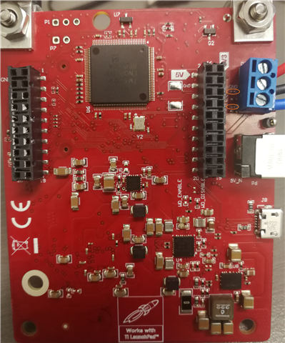
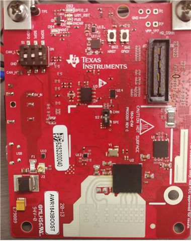
I want to play my AWR1843BOOST EVM with an external device through UART interface. I would like to keep the existing UART communication which is used for control in TI demos and add another UART interface on the board.

Is it possible to create second UART interface? Could you please give me some guide about the HW change and SW example/demo for this use case?

Kind regards

Ree  

  • Hi Ree,

    On AWR1843BOOST, two UARTs are emulated over USB (via xds110). And both of these are being used by mmw demo. Point to note here that one of UART has Rx and Tx :RS232-UARTA (emulated as Application/User UART COM port) whereas other UART has only Tx: MSS_logger-UARTB (emulated as Auxiliary COM port).

    So if you need AWR application to just send object data then use MSS_Logger UART and move other UART (RS232) with external board for communication with AWR device. Make sure that you do the right pinmux for this setting, follow the mmw demo which does the pinmux for these UARTs.

    For your purpose you can bring out these UART lines on AWR1843BOOST Header pins and from there connect with your external MCU over cable.

    Follow below pictures from AWR1843BOOST schematic (https://www.ti.com/lit/zip/sprr370

    where you need to connect 0ohm resistors to bring UART lines to EVM headers.

    On the other hand, it is also possible to get Rx and Tx features for both of the MSS UARTs. For that you need to do additional ECO (resistor connection) and Pinmux.

    That requires additional pin for UARTB_RX function which was missing in above solution.

    You need to do pinmux of pin P4 to UARTB_Rx function,

    Snapshot from sysConfig tool to generate pinmux code. https://dev.ti.com/sysconfig/#/config/?args=--device%20AWR18XX%20--part%20Default%20--package%20Default%20--theme%20light

    Pin P4 is by default muxed to SYNC_IN on AWR1843BOOST (check in above 1st snapshot) which can be overridden to UARTB_RX by pinmux (code generated by sysConfig tool)

    // Pinmux_Set_OverrideCtrl(SOC_XWR18XX_PINP4_PADBB, PINMUX_OUTEN_RETAIN_HW_CTRL, PINMUX_INPEN_RETAIN_HW_CTRL);
    Pinmux_Set_FuncSel(SOC_XWR18XX_PINP4_PADBB,SOC_XWR18XX_PINP4_PADBB_MSS_UARTB_RX);

    // Pinmux_Set_OverrideCtrl(SOC_XWR18XX_PINF14_PADAJ, PINMUX_OUTEN_RETAIN_HW_CTRL, PINMUX_INPEN_RETAIN_HW_CTRL);
    Pinmux_Set_FuncSel(SOC_XWR18XX_PINF14_PADAJ,SOC_XWR18XX_PINF14_PADAJ_MSS_UARTB_TX);

    And additionally you need to solder 0ohm resistor next to J6:9  (R165) of the EVM to bring that UARTB_RX to header.

    Hope these information would help you to achieve your development.

    Regards,

    Jitendra

  • Thank you very much Jitendra!

  • Hi Jitendra, 

    I could not find R165 on the board. It seems nothing next to J6:9. I find R169, R166 and R26 as that in attached pictures.

    Kind regards

  • Hello Ree,

    If you look at AWR1843BOOST assembly file then you can find the location of each resistors.

    Marked in below picture.

    Regards,

    Jitendra