This thread has been locked.

If you have a related question, please click the "Ask a related question" button in the top right corner. The newly created question will be automatically linked to this question.

LMP91000EVM: Data readout using arduino mega 2560 for cyclic voltammetry

Part Number: LMP91000EVM
Other Parts Discussed in Thread: LMP91000,

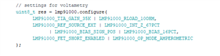
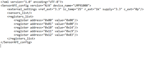
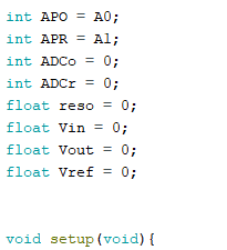
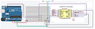
Hello, I am using the LMP 91000EVM to collect data and process it using an Arduino mega 2560. The .ino used for cyclic voltammetry was found in the linked GitHub under the LMP91000/examples/CyclicVoltammetry/ directory. The attached pdf contains the schematic for the sensor, where wires were connected to headers on the SPIO-GPSI16 connector. The wires were connected following the list in the ReadMe.md and Vref/Vout data presented on the monitor and plotter. However, the output was not changing when the CE/WE/RE electrodes were being tested. This was done by changing the spacing between them and testing within water.

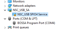
Would anyone be able to help in solving this issue? Photos of the physical wiring will be uploaded later on, and I would also like to know if it may just be an error in the code I am using or the way I am trying to use it. The primary reason an SPIO-4 board is not being used is the one available for use does not successfully connect with computers using current versions of Windows. I have attempted to use all available drivers and software versions provided but have not been able to get the sensor to show within the software. I also do not have enough time to receive a replacement even if that option was still available for it. If you need any additional information feel free to ask as well

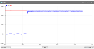
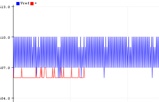
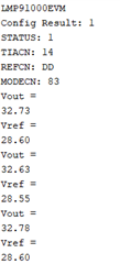
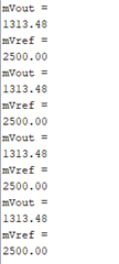
Images are of monitor and plotter output 

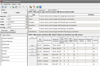
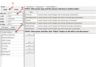
These are the numbers shown in the monitor when run, far left image was in the first run. The middle and right images are from a rerun at different times.

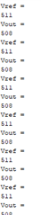
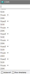
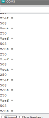
The data in the monitor is consistent and unchanging however, the data on the plotter below varies wildly but I have not noticed any causes for these changes in the Vout. The first image was during the initial part when the code is run, with the image after showing how it looked with more time passing. This was all randomly happening with no correlation to the electrodes.

LMP91000EVM User's Guide Rev2.4.pdf

  • Ali,

      From what I can see, The ADC is reading a value equal to half of the VREF. This is the correct value you would expect from VOUT. Most likely you do not have the EVM configured correctly for your probe. 

    The sensor manufactures have standard settings for their sensors. However standard settings don't always apply to every design or IC that can be used to measure the sensor. The LMP91000 is a transimpedance amplifier that is very sensitive and low current.

    Most designers, begin with the incorrect settings for the LMP91000 board. I realize that you are not using the SPIO-4 , however use the GUI Software that was created for the EVM to find a sensor that is similar or the same as you are using and change the default settings to these values to begin. Only if you are using a standard solution with the sensor can you know exactly what value you should be getting. Adjust the settings until you get the correct voltage feedback. 

  • Hi Gordon,

    How would I use the software for the EVM if I am unable to interface it with any available computers? As this is my first experience with these devices I do not know how to troubleshoot them for my situation. Would you be able to advise on how I would be able to configure it as I have attempted to connect using the software on the product support page and an SPIO-4 with no success. 

    All available drivers and software I have seen on forum pages have not worked, so any help would be appreciated

  • Ali,

      The GUI will run without the SPIO-4 or EVM. The intent is to find a similar sensor or the exact sensor that your are using. Then use the recommended setting to configure your sensor. If you are trying to use the EVM with the Arduino mega 2560 and have not configured the sensor, that would explain why it's not working.

  • When you refer to GUI, I am assuming you mean the software available on the product page.

    Is the screenshot what you mean by finding a suitable sensor and the data in the table used for configuring the sensor. Could you advise on how to then configure the sensor, I will also be attempting to use the SPIO-4 board again in the attempt to solve the issue through the software.

  • Ali,

    To use the GUI, first select the LMP9 device, then setup the parameters, then select the type of sensor and pick the closest sensor to the one you are using.

    Go through the tabs on the left. Once you have configured the setup, select save configuration. The xml file that is saved will have the register information you need to begin. Use the data sheet to understand what each register is for. You have to write to the EVM to configure it for your sensor.

    Please used the tutorial to learn how to do this. 

  • Thanks for the quick response,

    I will have an attempt at this, as this is my first time doing cyclic voltammetry would you be able to suggest the initial parameters to be set. For the sensor choice, I will have to discuss it with my supervising lecturer. Thank you again for your help and I will update you on the progress.

  • I have just gotten my hands on an available SPIO-4 board however it does not register within the device manager after having installed signed and unsigned drivers. This was done in both a normal boot of windows and after having disabling driver signing.

    This is how the devices are displayed, for right now I am attempting to get the SPIO board to register as the NSC device instead of the Bossa port. Is it possible to flash the Atmel using a flash programmer in order to get it working again? Unless there is another alternative way of fixing this issue as for now I am getting a code 10 error for the device. 

    Settings within the lmp91000 GUI have also been set now and saved within configuration files but cannot be uploaded because no hardware is being detected. I will continue troubleshooting but deadlines are approaching so any more help would be appreciated.

  • Ali,

      TI has released a version of drivers awhile back to fix the driver issue. Microsoft has updated Windows that makes these drivers very difficult to install. Many customers are having this problem. We have a team working on updating the drivers yet again. I have no idea how long it will take.

    My suggestion for now is to forget the SPIO-4 board. Use the Arduino mega 2560 board and code. So far the code talks to the LMP91000EVM. That is a good start. You will need to write the new code to initialize the LMP91000 for the sensor that you are using. The old GUI will help you to configure the registers. You need to write code to put the register values into the LMP91000. 

    You need to get help from a student programmer or write the code yourself. Until you select a sensor, configure the EVM to use the sensor and then read back VOUT signal and verify that the measurements are correct based on using a standard to verify an accurate measurement, you won't be able to do any of the cyclic voltammetry that you want to do.

    I apologize that it's not easy or plug and play, and that we are having issues with Microsoft and our drivers. If you want to do this, you will need to put in the time and engineering to make it work.

    I will be happy to offer suggestions and help as I can, but you will need to read up and figure this out. 

    I will be traveling the next few days so my responses will be a bit delayed, but I will get back to you for support as soon as I can.

  • Hi Gordon,

    I will follow your suggestion and go back to working on the Arduino. I have found files in this GitHub: https://github.com/WickedDevice/LMP91000 that allow for the configuration of the registers on the lmp91000. At this current time, I have set the configuration in the setup of the code to match the configuration from the AFE GUI using presets defined in the lmp91000.h file on GitHub.

    There is a small problem with one of the HEX outputs as it shows in the Arduino serial monitor as 0xd9 instead of what should be shown: 0xc9. I will fix this and attempt to write up the code with the help of another student and technician for the loop section. I will also look into the datasheet of the ADC as well for any potential points of information.

    Thank you for all the help you have given so far, I will update this thread when progress is made.

  • Ali,

     Please keep me up to date. I like that you are learning this, maybe a bit of the hard way, but that is the fun of engineering. Always learning. 

    Remember if it was easy, anyone can do it. Try to enjoy the experience.

  • These are the variables defined to perform calculations in the Void Loop section. 


    void loop(void){

    //12-bit 4096
    //16-bit 65536
    // ADC res/ Sys V = ADC read/Analog V Measured
    // Vmeasured = (Sys V/ADC res) * ADC read (convert sys V to mV)
    //variables assigned values

    reso = 65536;
    Vin = 3300; //in mV
    ADCo = analogRead(APO);
    ADCr = analogRead(APR);

    Vout = ((Vin)/(reso))*(ADCo);
    Vref = ((Vin)/(reso))*(ADCr);

    //Serial.println("ADC Vout = ");
    //Serial.println(ADCo);
    //delay(1000);

    //Serial.println("ADC Vref = ");
    //Serial.println(ADCr);
    //delay(1000);

    Serial.println("Vout = ");
    Serial.println(Vout);
    delay(1000);

    Serial.println("Vref = ");
    Serial.println(Vref);
    delay(1000);

    }

    The above lines were added to the test code found within the GitHub mentioned previously. I have tested the communication with the board via I2C using the built-in Arduino example sketch for device detection. After altering the configuration settings within the setup section to the settings set within the LMP91000 GUI, a number similar to the data in the earlier serial monitor images was displayed again. This additional code converts the ADC output read by the A0 pin on the Arduino to a measured analog voltage assuming everything goes smoothly. 

    Further updates will be posted with future alterations to the code and the connections between the Arduino and the LMP91000EVM. I want this thread to act as a guide for those looking to do the same thing but have not found a solution. 

    Current output in serial monitor is supposedly in mV however more tuning is required:

  • I believe the conversion I am trying to use to convert the outputs from the Vout and Vref test points are incorrect. 

    Vout = (Vref_div (internal to LMP91000)) - (RTIA (gain) x Iwe) (https://e2e.ti.com/support/sensors/f/sensors-forum/874340/lmp91000-afe-output-voltage)

    The above formula was found in another post but I do not understand what "IWE" is for and how the current data being read is used within it. 

  • Ali - 

    Iwe is: 

    I = current

    we = subscript indicating Working Electrode

    Ohms law....V (or E, depending on your school of thought) = I x R

  • Thank you for the fast reply, I have also figured out that with how I am linking the Vout and Vref points directly from the LMP91000 to the Arduino A0 and A1 pins respectively. I was using information for the ADC on the evaluation board but since I am bypassing it I need to redo some of the numbers in the void loop.

    the output of the serial monitor, Vref when measured with a multimeter matches what is shown on

    How would I calculate or read the current produced by the working electrode as I have functionally now gotten voltage to be read. To create the graphs in cyclic voltammetry I would need to be able to read the current and be able to control the voltage but I cannot tell how that would be done.

  • I believe this image shows simply where the voltage is controlled, and current measured. 

    https://www.researchgate.net/figure/A-simplified-circuit-for-cyclic-voltammetry-Set-Up_fig1_329014747 

    in this case, with the LMP91000, the working electrode will the connected to the transimpedance amplifier, which is converting the current that you would otherwise be measuring directly to a voltage that you can read with DVM or ADC. You can back calculate the current, based on the Vout and the gain settings you have made to the part. 

    if you are able ever to use the GUI, it will tell you the output voltage, or the current and graph it for you. 

  • As I am not using the SPIO-4 board I am unable to connect the LMP91000 to the GUI, however, my RTia is set to 35K Ohms following my configuration of the sensor in the Arduino IDE. Would I just use a simple V=I*R formula to convert it back or the formula mentioned above? If it is the one above, then it should be:

    Vref Divider = 24%

    Vinternal = I'm assuming it is my 3.3V input at the GPSI connector, but my Vref reading is 2.5V which I guess is because it is bipolar (+/- 2.5V)

    Vout = (0.24 * Vinternal) - (35k Ohms * Iwe ) 

    Therefore to solve for Iwe, it should be:

    (Iwe)  =  ((0.24 * Vinternal) - Vout) / 35k Ohms


    If this is correct then I will include this calculation within my IDE code and post the results of the graphs created for verification if possible. Following the completion of this project, a Github will be created with the code used and instructions for use with it being tagged as the solution for those facing similar problems.

  • Ali,

      While you are mostly correct, the conversion from current to voltage is based on the gain.

    3-Lead Amperometric Cell = Gain=RTIA

    2-Lead Galvanic Cell = Gain= 1+(RTIA/RLoad) 

    The transimpedance amplifier uses an op-amp and a feedback resistor to generate an output voltage that is proportional to an input current.
    The magnitude of the gain is equal to the feedback resistance, and since inversion occurs, the circuit’s transfer function is
    VOUT= Iin×Rf
    Like a resistor, a transimpedance amplifier converts current to voltage, but unlike a resistor, it has low input impedance and low output impedance even with very high gain.
    A compensation capacitor connected in parallel with the feedback resistor is used to ensure stability in sensor applications.

    If you know what current you should have at a specific level based on the sensor, you should use a standard solution to verify and calibrate your formulas. Everything else is a good guess. 

    Remember the temperature will impact every measurement. Use the measured temperature at the voltage you measure based on the standard. Use a second standard solution to get a second data point, and measure both at different temperatures to get valid data points. Then you will be able to calculate the measured values not from current but from the ADC voltages. It will be faster and more accurate.

  • The issue for me now then is converting the ADC voltages. I have found a formula but I do not know how applicable it is for the given scenario:

    I = (ADC O/P) * ((Vref/ADCres)/(gain*R)       [I would guess Rload is substituted for R]

    I will discuss with my peer about the current that should be seen but a set solution is already being used for testing (milk for now, with proper testing on a BSA  solution. I will also keep in mind to vary solution temperature and attempt it. Would you suggest a large temperature variation (Troom:25C to 100C) or a minor increase

    Another question would be is there a way to directly plot a CV graph or would I have to do it manually?

  • Ali,

      Stay within a normal operating range for the temperature delta. 25C and I wouldn't think you would heat milk to 100C, so maybe 35C. it should be enough to determine a correction method to compensate for temperature.

    The gain is based on the feedback resistor and the input (load resistor). Research op-amp gain to understand how to determine the gain of the transimpedance amplifier.  

    You should be getting pretty close to understanding what you need for this test.

  • I am making good progress with this project now, it is just a matter of implementing the right code for plottable data. I will also test this correction method this Monday read into op-amp gain to make some more progress. Just for clarification, what is meant by internal zero?

  • Ali,

      The internal zero is half the reference. i.e... If Vdd is 3.3V, and the Vdd voltage is applied to the reference pin. This voltage is divided in half internally. The divided reference is 1.65Vdc and applied to the op-amp. It sets an internal zero for the sensor. All measurements above 1.65Vdc are positive and all measurements below 1.65V are negative. The internal zero allows measurements positive and negative without having a positive and negative power supply to read negative values. All measurements referenced to the internal zero are relative values. 

  • Thanks for the clarification and all of the help you have given. As the deadline is fast approaching for submission, I will be handing over the project to another peer with all the information provided and researched. Hopefully, in the future this project will be finalised.

  • Ali,

      Your welcome and good luck. I will close this ticket.