This thread has been locked.

If you have a related question, please click the "Ask a related question" button in the top right corner. The newly created question will be automatically linked to this question.

BOOST-TUSS4470: BOOST-TUSS4470 + MSP-EXP430F5529LP

Part Number: BOOST-TUSS4470

Hello guys!

I have a BOOST-TUSS4470 + MSP-EXP430F5529LP setup. My goal is to burst pulses using TUSS4470 to excite a transducer in a Pulse-Echo scheme. So it is quite important for me to have control over the excitation pulse frequency. However, I have not reached my goal using this setup so far!

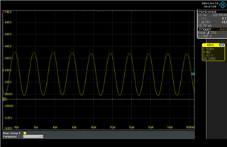
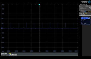
I have connected the OUTA & OUTB pins of the module to an oscilloscope and tried to modify the Frequency and NO. of pulses in the GUI environment. The problem is changing the parameters in GUI does not change the output signal of the OUTA & OUTB!

Initially, I was using the transducer of the board and someone suggested that this is the reason I cannot observe any change since the transducer's resonant frequency is around 40KHz. However, I tried transducers with different resonant frequencies and the problem consisted. 

But this is not the only problem I'm experiencing; exciting a transducer is commonly done with a square wave, but what we see in the output of the TUSS4470 is not even close to a square wave. 

Our goal of using the TUSS4470 is to miniaturize the electronic part of our design with a small, MCU-compatible chip. I would appreciate it if you could help me with this issue and correct me if our expectation of the board is way different from what this chip is originally designed for. 

Thank you,

Sajjad Mirbakht.

  • Sajjad,

    Thank you for your inquiry.  The intended use of TUSS4470 is to be able to drive an ultrasonic transducer for variable number of pulses at the resonant frequency of the transducer. 

    Can you provide any information on the specifications for your transducer?  What frequency are you attempting to set in the GUI? How many pulses are you setting? Can you provide details what method you are using to change the frequency (register map/run options)? Could you send a snapshot of your settings?

    Please also do review these resources which may be helpful:

    Ultrasonic FAQ with a quickstart guide video for TUS44X0 EVM

    https://e2e.ti.com/support/sensors/f/sensors-forum/748143/faq-ultrasonic-sensors

    Ultrasonic usage and optimization:

    https://www.ti.com/lit/an/slda058/slda058.pdf

    E2E forum regarding setting the frequency and adjusting CFLT & CINN capacitors 

    https://e2e.ti.com/support/sensors/f/sensors-forum/912757/boostxl-tuss4440-missing-documentation-to-set-frequency

    thank you,

    Scott

  • Dear Scott, 

    Thank you for your kind reply.

    My problem is solved now, I can change the Frequency and No. of Pulses in the GUI and observe the signal change in the Oscilloscope. (I attached the results so maybe they can be useful for someone working with TUSS4470).

    However, I would like to ask another question and I would appreciate it if you can help me with this question as well; is there any chance to change the 1) time intervals between the loops* and 2) pulse duration of the burst signals using TUSS4470?

    regards,
    Sajjad

    *By saying time intervals between the loops, I mean the time between the pulses illustrated in the third attached image (the blue one).

    Frequency:5KHz, No. of Pulses: 16Frequency:1MHzPulse Config.

  • Sajjad,

    The loop function is built into the GUI and not specifically a function of the device. I believe this delay you are observing may be controlled by the GUI software or firmware of the EVM. In your final application, you should be able to configure the device following this behavior

    It is even possible to setup the device in a continuous burst mode where you may use one device to provide continuous bursts and a second device only listens.  In this case, you do want to be sure to ensure that the transducer you select is rated for this use.  

    The burst pulse width is governed by the frequency of the clocks on the IO1 and IO2 pins, and should ideally be set to achieve a frequency which matches the transducer resonance.

    For the EVM, this is connected to the MCU on the booster pack

    Thanks,

    Scott

  • Thank you Scott, 
    I do appreciate your time and your great help.