This thread has been locked.

If you have a related question, please click the "Ask a related question" button in the top right corner. The newly created question will be automatically linked to this question.

TDC7200: Used for measurement of frequency of LDC1101 in DRDY mode

Part Number: TDC7200
Other Parts Discussed in Thread: LDC1101, TDC7201, LDC1001

Hello There,

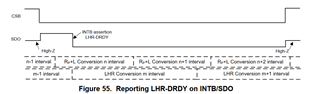
as described in SNOA941A I would like to use TDC7200 with LDC1101 in DRDY RP+L mode for time measurement between DRDY assertion. 

Topic A:

For best possible accuracy I read in manual for TDC7200 SNAS947D in section 8.4.5 START and STOP Edge Polarity that ideally:

  •  ... same edge polarity for the START and STOP input is highly recommended. - that is easily achievable since LDC has always pulse (rising and falling edge) for START and even for STOPs in DRDY mode.
  • it's strongly recommended to choose for the START and STOP signal the "rising edge".  - unfortunately this is not a choice in DRDY mode. Time (conversion) is measured always between falling edges.

I would like to know recommendation for this configuration and some estimate of INaccuracy.

Q1: What is degrease of accuracy when reading timestamp between falling edges instead of rising edges?

Q2: Would you recommend to use some kind of invertor (SN74LVC...) connection to invert pulses of DRDY assertion from LDC1101 to get recommended rising edges or it would bring more inaccuracy than actual measurement of falling edges just by TDC7200?

Topic B:

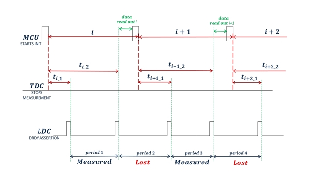
Also based on measurement nature of TDC and LDC in DRDY mode, it is unclear how to set TDC in order to continuously get conversion results from LDC1101. Once one conversion period is completed ideally the TDC should start immediately to measure next time between DRDY assertions in order not to loose any conversion period of LDC which it results in lost of every other conversion period.

Q3: How to achieve continuous conversion without loosing any single measurement period? 

Q4: Can TDC continue to measure for example second stop while first measurement data are being read by MCU? 

Q5: How it then deals with calibration measurements? (same calibration used for two measurements)

Using two stops may work in matter: While a 1st-stop-data are being read a 2nd-stop-data may be measured and then it may swap for reading 2nd-stop-data and measuring 1st-stop-data again. I do see here a problem that it will have to eventually loose one conversion of LDC in order to reset the TDC. Am I correct or there is a way to avoid it? Using two channel TDC7201 or so...

Thank you.

Best Regards,

Michael 

  • Hi Michael,

    Thank you for posting to the Sensors forum. 

    I am looking into this but will need more time in order to answer your questions. I expect to be able to respond by the end of the day on Wednesday.

    Best regards,
    Nicole

  • Hi Michael,

    I am still working on getting more information to answer your questions regarding the rising and falling edge accuracies.

    You mentioned measuring a second Stop signal, however the LDC can provide 1 pulse when a conversion is completed. How would the second Stop pulse be generated? Are you able to provide a block diagram of how this will be implemented, as well as where the Start and Stop pulses will be generated from? This will help me further understand your system implementation.

    Best regards,

    Nicole

  • Hi Nicole,

    I will describe it in this way: We need to measure continuously similar to LHR mode but with higher resolution (LHR mode capable of 1/32 MHz = 31.25 ns). In LHR mode every completed conversion period was indicated on the SDO pin by reporting LHR_DRDY which happens once the conversion period is successfully completed. After this interrupt is recognized by MCU, LHR data are read, BUT LDC continues to measure next conversion period while previous period is read out by MCU over SPI. This ensures that every conversion is retrieved from LDC and no conversion period is lost.

    I want to achieve same in DRDY in RP+L mode with external TDC7200 measurement. But it seems that every new measurement in TDC7200 always has to be initialized by MCU (sending START) and that cannot be done before previous data are read out from TDC7200. Correct?

    LDC continuously converts next period which cannot be measured since TDC needs to be initialize for a new measurement. We then loose information how much time passed from last conversion completion. 

    This causes that every other conversion period is lost due to nature of this measurement. Please see following pictured to better understand what I have in mind. 

    Please correct me if I am wrong.

    Thank you.

    Best Regards,

    Michael 

  • Hi Michael,

    As the LHR measurements of the LDC1101 have an effective external frequency of 32 MHz, using the TDC7200 for higher resolution measurements will not offer significant improvements. As such, this method is recommended for use with the LDC1000.

    In this case, I would recommend testing the system to confirm if there is lost data. Figure 5 in SNOA941A shows the timing diagram with 5 Stops from the LDC. It may not be necessary to have multiple Starts from the MCU, if this continued initialization ends up to be causing issues.

    Best regards,

    Nicole

  • Hi Nicole,

    As the LHR measurements of the LDC1101 have an effective external frequency of 32 MHz, using the TDC7200 for higher resolution measurements will not offer significant improvements. As such, this method is recommended for use with the LDC1000.

    Q7: Can LDC1001 with TDC7200 measurement achieve higher resolution in same conversion time as LDC1101 in LHR mode?

    Q8: Can LDC1101 in DRDY mode achieve higher resolution with MCU timer periphery as method 1 in SNOA941A than same conversion time with LHR mode?

    Q9: Is the precision of event counter (DRDY assertion) in LDC IC influenced by reference frequency so the TDC7200 will now help since the error of measurement is already influenced by LDC before actual time measurement happen?

    In this case, I would recommend testing the system to confirm if there is lost data. Figure 5 in SNOA941A shows the timing diagram with 5 Stops from the LDC. It may not be necessary to have multiple Starts from the MCU, if this continued initialization ends up to be causing issues.

    Yes, 5 STOPS is max number of STOPS that TDC7200 can measure from single START. But after 5 STOPS it needs to be reset with new START.

    In case of 5 STOPS the latency of such a measurement will be 5 conversion period since the data cannot be read until the end of measurement. In this case it will loose every (N+1)th conversion period, where N is number of STOPS and the latency is N conversion period + data read out.

    In case of 1 STOP each 2nd period is lost and the latency is single conversion period + data read out. In case of 5 STOPS it looses every 6th conversion period and the latency is 5 conversion periods + data read out. Correct?

    To have minimum latency it needs to read out after every STOP I believe.

    Let me know whether I correctly understand functionality.

    Thank you.

    Best Regard,

    Michael

  • Hi Michael,

    I will need to test this application in the lab in order to answer your questions regarding resolution, as well as to confirm the behavior of the system.

    I expect to have answers and to be able to update this thread by the end of the day on Tuesday.

    Best regards,

    Nicole

  • Hi Michael,

    The LDC1101 in LHR mode will still have a higher resolution than the LDC1001, as the LDC1101 has an effective resonance frequency of 32 MHz. However, the maximum supported reference frequency for the LDC1101 is 16 MHz. The best timing resolution for the LDC1101 as listed in Method 1 is 62.5 ns, compared with 125 ns for the LDC100x. In DRDY mode the LDC1101 gives better resolution since it still supports LHR mode.

    Additionally, I do not believe that the precision of the DRDY assertion will be improved by the TDC7200. Using DRDY reporting in LHR should give the best resolution.

    Best regards,
    Nicole

  • Hi Nicole,

    thank you for your discoveries.

    The LDC1101 in LHR mode will still have a higher resolution than the LDC1001, as the LDC1101 has an effective resonance frequency of 32 MHz. However, the maximum supported reference frequency for the LDC1101 is 16 MHz. The best timing resolution for the LDC1101 as listed in Method 1 is 62.5 ns, compared with 125 ns for the LDC100x. In DRDY mode the LDC1101 gives better resolution since it still supports LHR mode.

    How can be DRDY assertion used in LHR mode for frequency calculation? It has constant LHR - DRDY assertion based on RCOUNT value. Can the RPL - DRDY be used for frequency calculation even in LHR mode?

    Additionally, I do not believe that the precision of the DRDY assertion will be improved by the TDC7200. Using DRDY reporting in LHR should give the best resolution.

    Sorry still not clear:

    Yes, assertion of DRDY cannot be improved by TDC7200 but the intervals between DRDY assertions may be used for frequency calculation which should give better frequency resolution when TDC7200 is used instead of LHR core. Correct?

    Thank you for helping.

    Michael

  • Hi Michael,

    Yes, you can use DRDY reporting in LHR mode. Section 9.1.14 of the LDC1101 datasheet has further details on this. You are able to indicate a complete conversion on the SDO pin by reporting the DRDY signal for both the RP+L conversion (RPL-DRDY) as well as LHR mode (LHR-DRDY).

    Yes, assertion of DRDY cannot be improved by TDC7200 but the intervals between DRDY assertions may be used for frequency calculation which should give better frequency resolution when TDC7200 is used instead of LHR core. Correct?

    For the LDC1101 the frequency resolution will not be significantly improved with the TDC7200, because LHR mode already has an effective reference frequency of 32 MHz. The DRDY timing method is recommended more for the LDC100x, as this device supports an 8 MHz reference.

    Best regards,

    Nicole

  • Hi Nicole,

    thank you for all the help.

    This resolved my issue.

    Thank you,

    Michael