This thread has been locked.

If you have a related question, please click the "Ask a related question" button in the top right corner. The newly created question will be automatically linked to this question.

IWR1642BOOST: How to enable the data transmission of "Azimuth Static Heat Map" and "Range Doppler Heat Map" in the object detection over CAN (ODOC) lab

Part Number: IWR1642BOOST
Other Parts Discussed in Thread: IWR1642

Hello, 

I have a question on enabling the data transmission of the  "azimuth static heat M=map" and "range doppler heat map" in the object detection over CAN (ODOC) lab.

As defined in the mss_main.c file, in default, 0xD1, 0xD2, 0xD3 and 0xD6 were enabled for data transmission over CAN. If I want to plot the heat map, I need to enable 0xD4 and 0xD5. My question is that how to enable or where to enable 0xD4 and 0xD5 for the heat map data transmission over CAN?

typedef enum mmwDemo_can_message_type_e
{
/*! @brief List of detected points */
CAN_MESSAGE_MMWDEMO_DETECTED_POINTS = 0xD1,         // 0xD1

/*! @brief Range profile */
CAN_MESSAGE_MMWDEMO_RANGE_PROFILE,                           // 0xD2

/*! @brief Noise floor profile */
CAN_MESSAGE_MMWDEMO_NOISE_PROFILE,                             // 0xD3

/*! @brief Samples to calculate static azimuth heatmap */
CAN_MESSAGE_MMWDEMO_AZIMUT_STATIC_HEAT_MAP,          // 0xD4

/*! @brief Range/Doppler detection matrix */
CAN_MESSAGE_MMWDEMO_RANGE_DOPPLER_HEAT_MAP,      // 0xD5

/*! @brief Stats information */
CAN_MESSAGE_MMWDEMO_STATS                                                 // 0xD6

} mmwDemo_can_message_type;

Thank you very much for the help!

Best,

Hang

  • Hello

    Have you looked at the CAN driver provided as part of the SDK.

    Thank you,

    Vaibhav

  • Hi Vaibhav,

    Thanks for reply. I checked the function Can_Initialized() in the mss_main.c file. 

    Can_Initialized() function initialized the transmission data rate 1Mbps/5Mbps, and set up the transmit message object with msgIdentifier = 0xD1. I think that's why I received the detected object data from 0xD1. However, I also received message from 0xD2, 0xD3, and 0xD6. I don't where the code setup this? If you can give me some hints in the code where the setup transmission for 0xD2, 0xD3 and 0xD6, maybe I can set up for 0xD3 and 0xD4 for the heat map data?

    Also, these two lines in Can_Initialized() are unreadable to me. Could you tell me what they are used for and how the params come from?

    CSL_FINSR(0x43201450, 22, 22, 0x1U);
    CSL_FINSR(0x4320140C, 26, 16, 0x23U);

    Thank you very much for your help!

    Best,

    Hang

  • Hi Hang,

    If you refer to the mmwDemo_can_message_type_e enum, you'll see the following.

    typedef enum mmwDemo_can_message_type_e
    {
        /*! @brief   List of detected points */
        CAN_MESSAGE_MMWDEMO_DETECTED_POINTS = 0xD1,
    
        /*! @brief   Range profile */
        CAN_MESSAGE_MMWDEMO_RANGE_PROFILE,
    
        /*! @brief   Noise floor profile */
        CAN_MESSAGE_MMWDEMO_NOISE_PROFILE,
    
        /*! @brief   Samples to calculate static azimuth  heatmap */
        CAN_MESSAGE_MMWDEMO_AZIMUT_STATIC_HEAT_MAP,
    
        /*! @brief   Range/Doppler detection matrix */
        CAN_MESSAGE_MMWDEMO_RANGE_DOPPLER_HEAT_MAP,
    
        /*! @brief   Stats information */
        CAN_MESSAGE_MMWDEMO_STATS
    } mmwDemo_can_message_type;


    Based on this, I believe the information that you are looking for is already output by this demo, which is why you are seeing extra ID's. I am not sure what registers that those writes are mapping to, but can look into it if you still are concerned with them. 

    Best Regards,
    Alec

  • Hi Alec, 

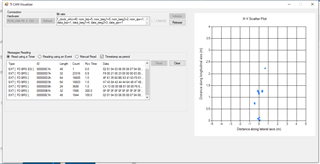
    Thanks for checking out this. I was using the ODOC lab demo with the PCAN CAN-FD USB converter. 

    Here is the screenshot. 

    Actually, I never get any data from 0xD4 and 0xD5. I am not sure why. I checked out the code MmwDemo_mboxReadTask() in mss_main.c which takes charge of sending data over CAN. However, I didn't figure out where it filtered out 0xD4 and 0xD5

    Another possibility is that the DSS does not sent heatmap data to the MSS through mailbox. However, in fuction MmwDemo_dssSendProcessOutputToMSS() of dss_main.c, it seems the DSS send the heatmap data to MSS through mailbox. 

    I am guessing something in the mss_main.c filters out the messages of 0xD4 and 0xD5 and they are not sent out through CAN. I haven't figured out. Any suggestions?

    Thanks again for the help!

    Best,

    Hang

  • Hi Alec,

    I just used PCAN CAN-FD converter to receive all the messages over CAN. I can confirm that the heatmap data of 0xD4 and 0xD5 were never sent out through CAN. The problem has become that where I should configure so that the messages of 0xD4 and 0xD5 can be sent out over CAN. 

    Best,

    Hang 

  • Hello

    Can you please confirm which demo llab is the  following code snippet from?

    Thank you,

    Vaibhav

    Thanks for reply. I checked the function Can_Initialized() in the mss_main.c file. 

    Can_Initialized() function initialized the transmission data rate 1Mbps/5Mbps, and set up the transmit message object with msgIdentifier = 0xD1. I think that's why I received the detected object data from 0xD1. However, I also received message from 0xD2, 0xD3, and 0xD6. I don't where the code setup this? If you can give me some hints in the code where the setup transmission for 0xD2, 0xD3 and 0xD6, maybe I can set up for 0xD3 and 0xD4 for the heat map data?

    Also, these two lines in Can_Initialized() are unreadable to me. Could you tell me what they are used for and how the params come from?

    CSL_FINSR(0x43201450, 22, 22, 0x1U);
    CSL_FINSR(0x4320140C, 26, 16, 0x23U);

  • Hi Vaibhav,

    Sure, it is C:\ti\mmwave_automotive_toolbox_3_2_0\labs\lab0005_object_data_over_can lab. 

    The code is in C:\ti\mmwave_automotive_toolbox_3_2_0\labs\lab0005_object_data_over_can\odoc-target\mss\mss_main.c file

    Best,

    Hang

  • Hang,

    I believe you can enable these additional options by going to the hardcoded .cfg inside of cli.c in the MSS project. Look for the guiMonitor command in this hardcoded config, and replace the two 0's with 1's. You can see the format for this command in mss_odoc_cli.c

    Let me know if you have further questions.

    Best Regards,
    Alec

  • Hi Alec,

    Thank you so much that works! I set "{"guiMonitor -1 0 0 0 1 0 0 \n\r"}" to only transmit 0xD4 (azimuth heatmap).

    However, I only received the data once and then the program seems stuck. My guess is that the heat map data is much larger than the detected points and the transfer rate was too high. Is there anyway I can adjust the transfer rate for per frame so that the program won't stuck and I can receive the heatmap periodically?

    Thanks!

    Best,

    Hang 

  • Hi Hang,

    A couple steps that I can recommend here. If you are unsure where the code is having issues, I would recommend debugging the code through CCS using developer mode. The steps can do this are located in {Automotive_Toolbox_Install_Dir}\mmwave_sdk_ccs_projects\common\docs\software_setup\using_ccs_debug.html

    If you feel confident that you just need to reduce the frequency for which you are sending heatmap data, I would recommend going to the MmwDemo_mboxReadTask function, into the case for MMWDEMO_DSS2MSS_DETOBJ_READY and checking the msgIdentifier to see if it's a heatmap, and then just use a counter and send it every X number of times you receive one. Let me know if this is unclear.

    Best Regards,
    Alec

  • Hi Alec,

    I did successfully receive the heatmap data from ID: 0xD4 when I lowered the framerate (to 5fps) in the settings of frameCfg. 

    My original thoughts were that the uart interface can only achieve heatmap data transmission at 5fps, would the CAN-FD interface be better than that?

    Actually, when I tested the IWR1642 with the mmWave visualizer (OOB demo), I achieved the data rate of uart for heatmap data up to 8 fps. 

    Then, I used the same settings from the profile.cfg file, hard coded it for the CAN-FD interface. The program stuck again. 

    From your expertise, is there any other reason that can block the data transmission or influence the transmission rate (except the settings of frameCfg)?

    I also attached the hard coded configuration in cli.c file. 

    Thanks a lot!

    Best,

    Hang

    uint8_t* radarCmdString[MAX_RADAR_CMD] =
    {
    //     % ***************************************************************
    //     % Created for SDK ver:02.00
    //     % Created using Visualizer ver:2.0.0.0
    //     % Frequency:77
    //     % Platform:xWR16xx
    //     % Scene Classifier:best_range
    //     % Azimuth Resolution(deg):15
    //     % Range Resolution(m):0.073
    //     % Maximum unambiguous Range(m):15
    //     % Maximum Radial Velocity(m/s):1.99
    //     % Radial velocity resolution(m/s):0.25
    //     % Frame Duration(msec):125
    //     % Range Detection Threshold (dB):15
    //     % Doppler Detection Threshold (dB):15
    //     % Range Peak Grouping:enabled
    //     % Doppler Peak Grouping:enabled
    //     % Static clutter removal:disabled
    //     % ***************************************************************
        {"sensorStop \n\r"},
        {"flushCfg \n\r"},
        {"dfeDataOutputMode 1 \n\r"},
        {"channelCfg 15 3 0 \n\r"},
        {"adcCfg 2 1 \n\r"},
        {"adcbufCfg -1 0 0 1 0 \n\r"},
        {"profileCfg 0 77 195 7 49.1 0 0 50 1 256 6250 0 0 30 \n\r"},
        {"chirpCfg 0 0 0 0 0 0 0 1 \n\r"},
        {"chirpCfg 1 1 0 0 0 0 0 2 \n\r"},
        {"bpmCfg -1 0 0 1 \n\r"},
        {"frameCfg 0 1 16 0 125 1 0 \n\r"},
        {"lowPower 0 1 \n\r"},
        {"guiMonitor -1 0 0 0 1 0 0 \n\r"},
        {"cfarCfg -1 0 0 8 4 4 0 5120 \n\r"},
        {"cfarCfg -1 1 0 4 2 3 0 5120 \n\r"},
        {"peakGrouping -1 1 1 1 1 255 \n\r"},
        {"multiObjBeamForming -1 1 0.5 \n\r"},
        {"calibDcRangeSig -1 0 -5 8 256 \n\r"},
        {"extendedMaxVelocity -1 0 \n\r"},
        {"clutterRemoval -1 0 \n\r"},
        {"compRangeBiasAndRxChanPhase 0.0 1 0 1 0 1 0 1 0 1 0 1 0 1 0 1 0 \n\r"},
        {"measureRangeBiasAndRxChanPhase 0 1.5 0.2 \n\r"},
        {"nearFieldCfg -1 0 0 0 \n\r"},
        {"CQRxSatMonitor 0 3 4 127 0 \n\r"},
        {"CQSigImgMonitor 0 127 4 \n\r"},
        {"analogMonitor 1 1 \n\r"},
        {"lvdsStreamCfg -1 0 0 0 \n\r"},
        {"sensorStart \n\r"}
    
    };


  • Hi Alec, 

    One more thing to mention, if I change the setting {"frameCfg 0 1 16 0 125 1 0 \n\r"} of 125 to 200. It will work. 

    The uart data rate is less than 1Mbps, the CAN-FD data rate is set to 5Mbps. That's why I was wondering if I can increase the data transmission rate for heatmap by leveraging CAN-FD interface. 

    Best,

    Hang

  • Hang,


    Understood, I would think that you would be able to achieve higher throughputs over CANFD as well. I would recommend that you use the CCS debug features in order to figure out where it is hanging.


    Best Regards,
    Alec

  • Hi Alec,

    Thank you so much! 

    After more tests, my conclusion is that even though CAN-FD is faster than UART, it cannot achieve high frame rate for heatmap data plotting. Both of them will work as high as 6-7 fps. 

    I have last two questions. 

    (1) For each frame data/each scan, if the detected object data is ready, the heatmap data is also ready in theory, right?

    (2) Can the DCA1000 with LVDS be used for plotting the heatmap data?

    Thanks a lot!

    Best,

    Hang

  • Hang,

    1. I believe this is correct, you can probably verify it by looking through the DSS project code.
    2. It can, but since the DCA1000 outputs raw ADC data, you would have to process it yourself. 

    Additionally, if you are just having a throughput issue, you could also modify the data output structures and remove any fields which you do not need. I'm not sure what fields you need, but if you trim the structures down to only include what you need (make sure you update any references in the code that fills the fields which you are removing) you may be able to increase the amount of frames you send out. 

    I am also very surprised to hear that there is a bottleneck in the CAN speed, do you have any way to validate whether the CAN bus is actually at 100% utilization? 

    Best Regards,
    Alec

  • Hi Alec,

    Thank you very much for your suggestions! Assume I just want the azimuth heatmap data. 

    From my testing, there are ~1.25KB for the detected objects and ~8KB for the heatmap of per frame scan (in my indoor environment).

    With both UART and CAN-FD interfaces, I can only achieve the azimuth heatmap up to 6fps. 

    Unfortunately, I don't have a device for validating the utilization of CAN bus. What I did was set the data rate of transmission as 5Mbps, the arbitration rate to be 1Mbps on both ends. 

    What I was guessing is that since the heatmap data and detected points from the radar are ready almost at the same time, the detected points can be used for plotting at up to 30Hz, the heatmap data can only achieve 6Hz. I think the inter frame time for transmitting heatmap data is not long enough for above 6Hz transmission. Maybe transmission rate is the key to improve the frame rate?

    Thanks!

    Best,

    Hang 

  • Hang, 

    I agree with your point, to me its odd however that you saw a bottleneck at the same heatmap frequency, considering the CAN bus should be significantly faster than the UART connection.

  • Hi Alec,

    From my understanding, the  MmwDemo_mboxReadTask() function in mss_main.c was used to received mailbox message from the DSS and send out data to PC by using either UART and CAN-FD. 

    The MmwDemo_dssSendProcessOutputToMSS() function in the dss_main.c was used to send out data from DSS to MSS whenever the data was ready. The MmwDemo_dssSendProcessOutputToMSS() function was called by MmwDemo_dssDataPathOutputLogging() function. 

    My last guess is that the dss was forced to transmitted the data to the mss periodically instead of a interrupt fashion. Was is possible? Or how can I verify it?

    I attached the configuration file I used in the cli.c file

        {"sensorStop \n\r"},
        {"flushCfg \n\r"},
        {"dfeDataOutputMode 1 \n\r"},
        {"channelCfg 15 3 0 \n\r"},
        {"adcCfg 2 1 \n\r"},
        {"adcbufCfg -1 0 0 1 0 \n\r"},
        //-----------------------------------------------------------
        {"profileCfg 0 77 7 7 58 0 0  68 1 256 5500 0 0 30 \n\r"},
        {"chirpCfg 0 0 0 0 0 0 0 1 \n\r"},
        {"chirpCfg 1 1 0 0 0 0 0 2 \n\r"},
        {"bpmCfg -1 0 0 1 \n\r"},
        // {"frameCfg 0 1 32 0 100 1 0 \n\r"}, // 10Hz does not work
        {"frameCfg 0 1 32 0 150 1 0 \n\r"},    // 6.6Hz works
        {"lowPower 0 1 \n\r"},
        {"guiMonitor -1 0 0 0 1 0 0 \n\r"},    // azimuth heatmap only
        {"cfarCfg -1 0 2 8 4 4 0 5120 \n\r"},
        {"cfarCfg -1 1 0 8 4 4 0 5120 \n\r"},
        {"peakGrouping -1 1 0 0 1 224 \n\r"},
        {"multiObjBeamForming -1 1 0.5 \n\r"},
        {"calibDcRangeSig -1 0 -5 8 256 \n\r"},
        {"extendedMaxVelocity -1 0 \n\r"},
        {"clutterRemoval -1 0 \n\r"},
        {"compRangeBiasAndRxChanPhase 0.0 1 0 1 0 1 0 1 0 1 0 1 0 1 0 1 0 \n\r"},
        {"measureRangeBiasAndRxChanPhase 0 1.5 0.2 \n\r"},
        {"nearFieldCfg -1 0 0 0 \n\r"},
        {"CQRxSatMonitor 0 3 4 127 0 \n\r"},
        {"CQSigImgMonitor 0 63 8 \n\r"},
        {"analogMonitor 1 1 \n\r"},
        {"lvdsStreamCfg -1 0 0 0 \n\r"},
        {"sensorStart \n\r"}

    Thanks a lot for the help!

    Best,

    Hang

  • Hang,

    If you want to check this, the easiest way would to do some sort of debugging in the MmwDemo_mboxCallback function to keep track of how often it is being called.

    Best Regards,
    Alec

  • Hi Alec, 

    I still cannot get it to work faster. I will continue work on that and let you know if I have better. 

    Best,

    Hang

  • Hang, 

    Sure. It may be challenging to understand exactly what is going on without being able to see the activity on the CAN bus fully. My key suggestion would still be to modify the structures that are being sent in order to remove any fields that you do not actively need, in order to reduce the amount of data being sent. If it's okay with you, can we go ahead and close this thread? If you continue to have issue, I would encourage you to create a new thread on the topic of dealing with this bottleneck. 

    Best Regards,
    Alec

  • Hi Alec,

    Sure, please close this thread. I will take your suggestion to work that. Thank you so much for the help!

    Best,

    Hang