This thread has been locked.

If you have a related question, please click the "Ask a related question" button in the top right corner. The newly created question will be automatically linked to this question.

LM26: VTEMP Output vs Actual Temp is Incorrect

Part Number: LM26

Hi,

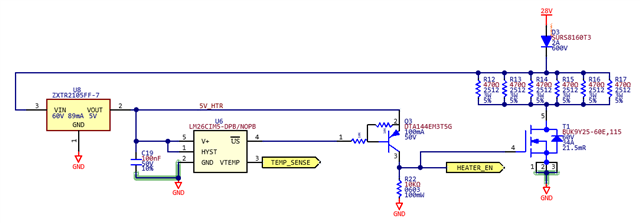
We are planning on using the LM26 in order to drive a circuit as a PCB heater when the temperature drops below -25C.

However, The LM26CIM5-DPB VTEMP Output (TEMP_SENSE) is steady at .96V which would correlate to ~110 degC but this is in a normal room environment ~25degC.

PCB Temp is ~30degC which should correlate to a VTEMP output voltage of ~1.8V. 

Is there something in my setup that would cause the output voltage to be stuck at an improper voltage?

Any thoughts or suggestions are helpful.

  • Hi Isaac,

    What is your VTEMP output connected to? As noted in section 8.3.2 of the datasheet the Vtemp output on the LM26 can only source 1uA of current at most. If the load capacitance seen by this pin is too large that could be the cause. 

    Best Regards,
    Brandon Fisher

  • Hi Brandon, 

    Forgot to mention that. VTEMP is connected directly to an ADC input of a micro (we just want to monitor the value / use it as an on-board temp sensor). The input capacitance on the pin to the micro is 8pF.

    Thanks,

    Isaac

  • Hi Isaac,

    Understood,. The LM26 should be able to drive that on its own.

    How are you verifying the voltage output in this case, are you using the MCU ADC or are you using a DMM or oscilloscope? 

    Best Regards,
    Brandon Fisher

  • Hi Brandon,

    We are reading back ADC counts in software and converting that to engineering values. We are then verifying whether this is correct by probing the output and ground pins of the LM26 with a DMM. I even used a thermal imager and infrared laser sensor to measure the temperature of the chip and it was still well under 30degC. 

    We have already resolved the previous issue of verifying the transfer function is correct through another forum post (LM26: Correct transfer function for VTEMP output - Sensors forum - Sensors - TI E2E support forums)

    What is even stranger is that when I put the part on a perfboard and run some wire-wrap wire to 5V, GND, and a VTEMP Output with a 10K on *US to 5V(V+) and the output voltage reads 1.8V which is correct so I know the part works. However the moment I connect just this VTEMP wire to the pad that goes to the Micro, it drops to around 0.96V-1V. I verified that there is nothing else on this VTEMP trace. 

    The Internal Pull-up or Pull-down on this pin of the micro is not enabled. So it sounds like the hardware is working in an isolated environment, and our software is reporting back the correct voltage/temp that it is seeing, but once the line is connected to the micro input something is causing the voltage to be pulled down on that line. Any other suggestions?

    Thanks,

    Isaac

  • Hi Isaac,

    Thank you for covering your troubleshooting so far. I agree you are converting this voltage correctly. Using this part should be this straightforward, as you've noted in your tests on perfboard. 

    Have you tried this with multiple boards? It does sound like you may have some leakage current at the input, given that the MCU pin is the only load and should have such little capacitance. Has this board been modified by hand, and if so, has it been cleaned thoroughly?

    I would recommend testing it with a series isolation resistor to see if that improves the output drooping. I would start with something around the datasheets largest recommendation of 8200 Ohm. 

    Best Regards,
    Brandon Fisher

  • Hi Brandon,

    Yes I can confirm this issue is on every prototype with the same voltage drop. There is a minor rework near this part but it has been cleaned and all the solder connections are strong. 
    I put a series 8.2k on this line and there is still no change in behavior. When nothing is connected to the MCU pin the MCU pin reads around 0.295V. Our software team says that they do not have the MCU internal PU or PD enabled (they are weak pulls anyway) so this should just be a floating voltage. Would adding a PU or PD on this line impact it do you think?

    The strangest part is that when the VTEMP output is connected to the MCU, the voltage line never changes from ~.9V but it does when I disconnect it from the MCU and have it floating independent from our PCB. The same behavior is observed even if the PCB part is lifted and the Perfboard circuit output is connected to the pad. 

    Our software team will try seeing if they slow down the sampling rate if that has any impact but otherwise I'm not really sure what else we can do. I may try jumpering it to a different open AN pin to see if there is something up with this particular input but I don't imagine that is the case. We may also try enabling the internal PU or PD to see what happens.

    Any other suggestions are appreciated.

    Thanks,

    Isaac

  • Hi Isaac, 

    What MCU are you using? Sometimes they specify an input leakage current, and I have seen these as high as 1uA on some older devices, which would be troublesome for an unbuffered ADC input connected to the LM26. 


    I'm not sure enabling the pullups/pulldowns would provide any benefit given the device output strength, but you can give this a try if you would like.

    The strangest part is that when the VTEMP output is connected to the MCU, the voltage line never changes from ~.9V but it does when I disconnect it from the MCU and have it floating independent from our PCB. The same behavior is observed even if the PCB part is lifted and the Perfboard circuit output is connected to the pad. 

    I may be misunderstanding you here, when you say the PCB part is lifted, do you mean the MCU is removed or the LM26 is removed? 

    Our software team will try seeing if they slow down the sampling rate if that has any impact but otherwise I'm not really sure what else we can do. I may try jumpering it to a different open AN pin to see if there is something up with this particular input but I don't imagine that is the case. We may also try enabling the internal PU or PD to see what happens.

    I think trying another ADC pin is a good idea, as that will eliminate any potential board level issues as the cause. A lower sample rate sometimes helps as well, this is typically most helpful when input capacitance is high. Please let us know if any of those techniques show an improvement.

    Best Regards,
    Brandon Fisher

  • Hi Brandon,

    We've tried all these options to no avail. We even tried connecting it to a PU or PD load resistor and then to a micro pin, as well as through an OPAMP and it just keeps getting pulled to a lower voltage than what it needs to be. It sounds like there isn't really much of a use-case for this pin from everything we've tried and it just doesn't make sense to us why it shouldn't work. Perhaps it was only really intended as being a pin to be referenced during calibration? Not sure.
    If there isn't any other errata that you know of, we will not be using this pin on the LM26 and will need to find another solution to getting on-PCB temperature reported to our MCU. 

    Best Regards,

    Isaac

  • Hi Isaac,

    Sorry to hear you are still having issues.

    I would expect buffering the LM26 output through most Op-Amps would be enough to prevent any voltage dipping. How are you connecting the LM26 and does the voltage when buffered also only dip when connected to your MCU ADC? 

    Best Regards,
    Brandon Fisher