This thread has been locked.

If you have a related question, please click the "Ask a related question" button in the top right corner. The newly created question will be automatically linked to this question.

TMUX1108: Sample code

Part Number: TMUX1108

Hello,

I am having issues with my TMUX1108.

Setup:

There are two TMUX1108's on my Arduino-type board, both sharing the A0, A1, and A2 pins, but with different EN pins.

Right now I am testing them with AA batteries (1.5v) ran to an ADC. 

Problem:

The problem is, even when I have my AA input only going through one channel, I am getting the same reading on all channels.

So I am experiencing my 1.5v signal on all of the channels, even on the other TMUX1108 when its enable pin is low.

However, if I read just a single channel, I will get the correct value on that channel and 0.0v on the other channels.

So it has something to do with calling all the channels.

I am pretty sure that I am not calling the address pins correctly, so I am in search of some C/C++ sample code.

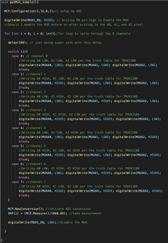
Here is a snippet of the code I am currently running with no success, but I've also included a screenshot thats easier to follow.

void setup(){

  Serial.begin(9600);

  pinMode(MUXA0, INPUT_PULLDOWN);
  pinMode(MUXA1, INPUT_PULLDOWN);
  pinMode(MUXA2, INPUT_PULLDOWN);
  pinMode(MUX1_EN, INPUT_PULLDOWN);
  digitalWrite(MUX1_EN, LOW);
}

void getMUX_Simple(){

  MCP.Configuration(1,16,0,1);// setup my ADC

  digitalWrite(MUX1_EN, HIGH); // Writing EN pin high to Enable the MUX
  //Should I enable the MUX before or after writing to the A0, A1, and A2 pins?

  for (int i = 0; i < 8; i++){//for loop to cycle through the 8 channels

    delay(200); // just being super safe with this delay
    
    switch (i){
      case 0: // channel 0
          //Writing A0 LOW, A1 LOW, A2 LOW per the truth table for TMUX1108
          digitalWrite(MUXA0, LOW); digitalWrite(MUXA1, LOW); digitalWrite(MUXA2, LOW); 
          break;
      case 1: //channel 1
          //Writing A0 HIGH, A1 LOW, A2 LOW per the truth table for TMUX1108
          digitalWrite(MUXA0, HIGH); digitalWrite(MUXA1, LOW); digitalWrite(MUXA2, LOW); 
          break;
      case 2: //channel 2
          //Writing A0 LOW, A1 HIGH, A2 LOW per the truth table for TMUX1108
          digitalWrite(MUXA0, LOW); digitalWrite(MUXA1, HIGH); digitalWrite(MUXA2, LOW); 
          break;
      case 3: //channel 3
          //Writing A0 HIGH, A1 HIGH, A2 LOW per the truth table for TMUX1108
          digitalWrite(MUXA0, HIGH); digitalWrite(MUXA1, HIGH); digitalWrite(MUXA2, LOW); 
          break;        
      case 4: //channel 4
          //Writing A0 LOW, A1 LOW, A2 HIGH per the truth table for TMUX1108
          digitalWrite(MUXA0, LOW); digitalWrite(MUXA1, LOW); digitalWrite(MUXA2, HIGH); 
          break;         
      case 5: //channel 5
          //Writing A0 HIGH, A1 LOW, A2 HIGH per the truth table for TMUX1108
          digitalWrite(MUXA0, HIGH); digitalWrite(MUXA1, LOW); digitalWrite(MUXA2, HIGH); 
          break;                
      case 6: //channel 6
          //Writing A0 LOW, A1 HIGH, A2 HIGH per the truth table for TMUX1108
          digitalWrite(MUXA0, LOW); digitalWrite(MUXA1, HIGH); digitalWrite(MUXA2, HIGH); 
          break;                
      case 7: //channel 7
          //Writing A0 HIGH, A1 LOW, A2 LOW per the truth table for TMUX1108
          digitalWrite(MUXA0, HIGH); digitalWrite(MUXA1, HIGH); digitalWrite(MUXA2, HIGH); 
          break;          
    }

    MCP.NewConversion(); //initiate ADC conversion
    ORP[i] = (MCP.Measure()/1000.00); //take measurement

    digitalWrite(MUX1_EN, LOW);//disable the MUX

  }

}
  • Hi Sam,

    When enable pin is low, all the channels will be OFF. When enable is high, depending on the A0/A1/A2 pin setting, only one channel will be ON at any given time out of the available 8-channels since this is a 1:8 Mux. 

    You can turn on EN after setting up A0/A1/A2 if you want predictability on the channel that is connected. You can also set the EN before setting up A0/A1/A2 but in this case the channel will be selected based on floating voltage/charge on these pins.

    I think your read variable or array is not setup correctly as the device functionality does not allow more than 1 channel to be ON at a given time.

    Thank you,

    Regards,

    Sandesh

  • Thank you for your answer.

    I have tried everything I can think of and it is still not functioning properly.

    I've even replaced the components.

    Can anybody provide me with sample code?

  • Here is the most simple code I could come up with and still no luck:

    const int MUXA0 = D3;
    const int MUXA1 = D4;
    const int MUXA2 = D5;
    const int MUX1_EN = D2;
    const int MUX2_EN = D8;
    
    void setup(){
    
      Serial.begin(9600);
    
      pinMode(MUXA0, OUTPUT);
      pinMode(MUXA1, OUTPUT);
      pinMode(MUXA2, OUTPUT);
      pinMode(MUX1_EN, OUTPUT);
      pinMode(MUX2_EN, OUTPUT);
      digitalWrite(MUX1_EN, LOW);
      digitalWrite(MUX2_EN, LOW);
      
    }


    void try89(int i){
    
      MCP.Configuration(1,16,0,1);// setup my ADC
    
      for (int i = 0; i < 8; i++){//for loop to cycle through the 8 channels
    
        delay(200); // just being super safe with this delay
        
        switch (i){
          case 0: // channel 0
              //Writing A0 LOW, A1 LOW, A2 LOW per the truth table for TMUX1108
              digitalWrite(MUXA0, LOW); digitalWrite(MUXA1, LOW); digitalWrite(MUXA2, LOW); 
              break;
          case 1: //channel 1
              //Writing A0 HIGH, A1 LOW, A2 LOW per the truth table for TMUX1108
              digitalWrite(MUXA0, HIGH); digitalWrite(MUXA1, LOW); digitalWrite(MUXA2, LOW); 
              break;
          case 2: //channel 2
              //Writing A0 LOW, A1 HIGH, A2 LOW per the truth table for TMUX1108
              digitalWrite(MUXA0, LOW); digitalWrite(MUXA1, HIGH); digitalWrite(MUXA2, LOW); 
              break;
          case 3: //channel 3
              //Writing A0 HIGH, A1 HIGH, A2 LOW per the truth table for TMUX1108
              digitalWrite(MUXA0, HIGH); digitalWrite(MUXA1, HIGH); digitalWrite(MUXA2, LOW); 
              break;        
          case 4: //channel 4
              //Writing A0 LOW, A1 LOW, A2 HIGH per the truth table for TMUX1108
              digitalWrite(MUXA0, LOW); digitalWrite(MUXA1, LOW); digitalWrite(MUXA2, HIGH); 
              break;         
          case 5: //channel 5
              //Writing A0 HIGH, A1 LOW, A2 HIGH per the truth table for TMUX1108
              digitalWrite(MUXA0, HIGH); digitalWrite(MUXA1, LOW); digitalWrite(MUXA2, HIGH); 
              break;                
          case 6: //channel 6
              //Writing A0 LOW, A1 HIGH, A2 HIGH per the truth table for TMUX1108
              digitalWrite(MUXA0, LOW); digitalWrite(MUXA1, HIGH); digitalWrite(MUXA2, HIGH); 
              break;                
          case 7: //channel 7
              //Writing A0 HIGH, A1 LOW, A2 LOW per the truth table for TMUX1108
              digitalWrite(MUXA0, HIGH); digitalWrite(MUXA1, HIGH); digitalWrite(MUXA2, HIGH); 
              break;          
        }
    
        delay(100);
        digitalWrite(MUX1_EN, HIGH); // Writing EN pin high to Enable the MUX
        delay(100);
        MCP.NewConversion(); //initiate ADC conversion
    
        Serial.printlnf("Channel %d: %.2f mV", i, (MCP.Measure()/1000.00)); //take measurement
    
        digitalWrite(MUX1_EN, LOW);//disable the MUX
    
      }
    }

    and here is the Serial output:

    Serial monitor opened successfully:
    Channel 0: 1227.19 mV
    Channel 1: 1195.44 mV
    Channel 2: 1211.19 mV
    Channel 3: 1586.12 mV
    Channel 4: 1141.31 mV
    Channel 5: 1169.56 mV
    Channel 6: 1225.75 mV
    Channel 7: 1211.25 mV

  • Hi Sam,

    I would suggest making sure the voltages and load you are applying to the device are correct. Would be a good idea to put a break point on the location where everything is setup (voltages and currents are set), and then take a multimeter or measurement instrument to the board you are using to ensure the device is being applied correctly (things to look for: correct VIH/VIL levels on your address pins for the channel you are selecting, VDD voltage is on, and input voltage to the S-pins is what you expect).

    Once completed, you should then step through your code and find out where things are beginning to read incorrectly instead of looking just at the end result.

    Thanks!

    Bryan