


The autonomous accessory detection IC line from TI are useful devices that will automatically route a 3 or 4 pole audio accessory based on the type of accessory detected. However, when implementing these devices into your system its crucial to understand how the accessories are working to maximize the utility of the part while also preventing design barriers from implementing the part in a sub-optimal configuration.
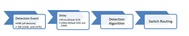
All three devices in the autonomous accessory detection IC line, the TS3A227E, TS3A226AE, and TS3A225E, use the same detection scheme. After a detection event has been triggered either through software or physical stimulus (like insertion of accessory) the IC will implement a delay period that defaults to 90ms for the 227E and 120ms for the 225E and 226AE. This delay can be changed in the 225E and 227E. Please see below for the chain of events from detection event to switch routing
After the delay a signal is generated at the tip pin and flows to both the RING2 and the SLEEVE pins on the IC which have a 3-bit ADC attached to them which then is used to measure the impedance between TIP and RING2 and TIP and SLEEVE. The 3.5mm Jack has the following structure along with common impedance ranges for the different accessory types.

The 3.5mm jack configurations that are shown in the datasheet can give an impression that the device is actually checking to see if the accessory type has the impedances shown. However, this is not the case. The device doesn’t care what the impedance values are, as what the device cares about is which impedance is larger TIP to SLEEVE or TIP to RING2. Based on the answer to that question the following outcomes are possible:
- SLEEVE_Z = RING2_Z à Route to a 3-Pole Accessory
- SLEEVE_Z > RING2_Z à Route to a Standard 4-Pole Accessory
- SLEEVE_Z < RING2_Z à Route to an OMTP 4-Pole Accessory
The reason that the switch can route by just comparing the values has to do how these protocols connect the different components of the 3.5mm plug.
In a 3-Pole device RING2 does not exist – but the RING2 connection is still made, but to the SLEEVE of the plug. This means RING2 and SLEEVE are shorted together and should have the same impedance.
In standard 4-pole devices the TIP of the 3.5mm plug is connected directly to RING2 via a resistance that is nominally 16Ω - 2KΩ. RING2 is then connected to the sleeve via a nominal impedance of 600Ω - 4kΩ. Since a signal from TIP has to pass through only one impedance to get to RING2 and it has to pass through two impedances to get to the SLEEVE. This forces the TIP to SLEEVE impedance to always register as more resistive than TIP to RING2 ideally.
In OMTP 4-pole devices it is the opposite of a standard implementation, so TIP is connected SLEEVE by one impedance and to RING2 by 2 impedances so TIP to RING2 is always going to have a higher resistance ideally.
Due to the low resolution of the internal ADC, 3 bits, the ADC is not as accurate as the designer may originally assume and this can potentially limit detection. These values are based off of the following ranges listed in the TS3A225E datasheet – however this applies to all three devices in the product line.
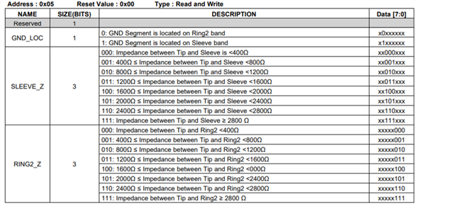
SLEEVE_Z is the impedance from TIP to SLEEVE and RING2_Z is the impedance from TIP to RING2_Z. The low resolution has two main effects. First, every value from 0b000 to 0b110 represents a range of 400Ω that means it is possible for values to be 399Ω apart from each other and still register as the same value. For example, an impedance of 1600Ω and 1999Ω will read as the same impedance value of 0b100. The second drawback is that the ADC saturates for resistances greater than 2800Ω so everything greater than 2800Ω will be registered as one value 0b111. and as a more extreme example of this is when the impedance puts the ADC into a saturation output. This can create situations where impedances of 3000Ω and 100KΩ would be registered as the same value 0b111. It is crucial to understand the accessory impedances planned to use with this device to judge whether or not the IC will support the device.
Even though there are impedance ranges listed – the device does not actually check if the device fits in the resistance range. It is only comparing path impedances – and if it can accurately compare the impedances the switches will be routed correctly. For example, if you have a device with a OMTP arrangement but the impedance from TIP to SEEVE is 2400Ω and the impedance from TIP to RING2 is 100KΩ the device would still route correctly. As it would read 2400Ω as 0b110 and it would read 100KΩ as 0b111 and TIP to RING2 is greater than TIP to SLEEVE. However, if TIP to SLEEVE was 3000Ω in the last example it wouldn’t route correctly as it would consider both impedances 0b111 (over 2800Ω).
The three autonomous 3.5mm accessory detection devices, TS3A225E, TS3A226AE, and TS3A227E, all use the same detection scheme which compares the impedances of the TIP to RING2 pathway and the TIP to SLEEVE pathway to judge what device has been inserted. Detection begins after the detection trigger is activated plus the debounce delay time in the device. To help with detection ensure that layout of all of the TIP, SLEEVE, and RING2 pins are all wide low impedance traces and as close as possible to the audio jack. It is also advised to not add additional components on these lines as this could impact detection.
Best,
Parker Dodson