This thread has been locked.

If you have a related question, please click the "Ask a related question" button in the top right corner. The newly created question will be automatically linked to this question.

TMUX1308-Q1: Is is larger than datasheet

Part Number: TMUX1308-Q1
Other Parts Discussed in Thread: TMUX1208

Hi Team,

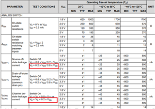
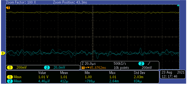
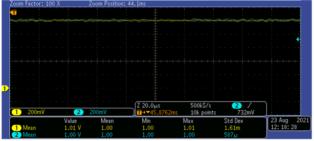
My customer test the Is current (result is uA)and found it is quite different from datasheet(nA).

Under various test conditions, the minimum leakage current at high temperature is several uA, and the maximum leakage current is tens of uA, which is much different from the datasheet 800nA.

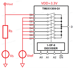
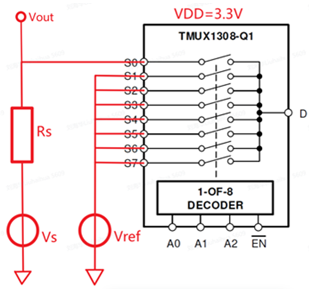
The test circuit is as following:

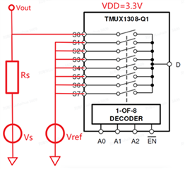
Rs=2k,Vs=0V,Vref=1.0V,The variable is temp

Temp of 1308/°C

△Vout/mV

Is/uA

Rs/kOHM

50

3.825

1.912021995

2.0005

60

7.275

3.636590852

2.0005

66

10.225

5.111222194

2.0005

70

13.2

6.598350412

2.0005

80

19.7

9.847538115

2.0005

90

27.475

13.73406648

2.0005

100

39.525

19.75756061

2.0005

105

45.6

22.79430142

2.0005

Rs=100k,Vs=0V,Vref=1.0V,The variable is temp

Temp of 1308/°C

△Vout/mV

Is/uA

Rs/kOHM

40

37.825

0.37825

100

50

55.225

0.55225

100

60

87.025

0.87025

100

70

119.175

1.19175

100

80

165.275

1.65275

100

90

204.175

2.04175

100

100

250.2

2.502

100

105

264.425

2.64425

100

110

289.55

2.8955

100

120

324.8

3.248

100

Rs=100k,Vref=1.0V,temp is 65℃,The variable is Vs

Rs voltage

△Vout/mV

Rs=100kOHM

Is/uA

0

61.531

100

0.61531

50

63.117

100

0.63117

100

57.515

100

0.57515

150

57.715

100

0.57715

200

51.795

100

0.51795

250

42.321

100

0.42321

300

35.403

100

0.35403

350

24.307

100

0.24307

400

12.71

100

0.1271

450

1.164

100

0.01164

500

-14.897

100

-0.14897

550

-39.376

100

-0.39376

600

-57.771

100

-0.57771

650

-80.305

100

-0.80305

700

-106.282

100

-1.06282

750

-128.505

100

-1.28505

800

-153.719

100

-1.53719

850

-188.735

100

-1.88735

900

-216.93

100

-2.1693

950

-250.29

100

-2.5029

1000

-280.373

100

-2.80373

Do you have some advice about how to achieve nA Is?

  • What are the voltages at the control inputs?

    This is not the same circuit as in figure 8-2 of the datasheet.

  • Amelie,

    As Clemens mentioned the circuit should look as section 8-2 in the datasheet


    Additionally, if Vdd is 3.3V, 1.0V and 0V won't match the test conditions in the datasheet. As you highlighted, the test conditions are Vs = 0.2*Vdd & Vd = 0.8*Vdd (or vice versa). This should be 0.66V and 2.64V. The control logic should be toggled to turn the switch off (/EN high), while the IC itself is still powered on. 


    Thanks,
    Rami

  • Hi Clemens and Rami,

    Customer is testing on-leakage current (as the right picture 8-3 in the following), not off-leakage current, which is 8-2.

    You could see that customer test situation is ok. Customer put “D” as floating.

    And because it is on-leakage, the /EN is Low.

    As you could see in the waveform customer tested, when S4 from not selected to selected, there are 20mV in S4. During on and off, S4 should have no voltage change, but now here is 20mV.

    Customer think this 20mV voltage jump is coming from the Is(on). And Is(on) go through the res and make 20mV.

    That is the reason why customer is very very concerned about Is(on). 

    By the way, customer also test TMUX1208 with the same method. And 1208 Is(on) is nA, which is the same as datasheet.

    Could you give some idea about why 1308 Is(on) is so larger?

    Please kindly give some advice! Here is customer SCH.

  • Amelia,

    Does every channel show similar results or only S4 and is this persistent across multiple chips? Could they run the test given the parameters from the datasheet? These are the conditions for how we've spec'ed it (below). However, their test conditions aren't data points we currently have for you to reference. I would like to see if the results are the same given the same tests in the datasheet.


    In the meantime, allow me a day or two to get lab results and see if I'm seeing the same thing. I will update you on Monday.

    Thanks,
    Rami

  • Hi Rami,

    Other channel are the same.

    In the figure 8-3 right side, there is no need to add Vd... Why datasheet parameters have Vd?

  • Looking forward for your test result.

  • Hey Amelie,

    I got into the lab today and ran tests in the same fashion as the customer did, with the same setup the customer ran (Vref = 1V 62kohm Rs):


    I didn't see what they were seeing. The △Vout was sub mV (~0.02mV) which would equate to a leakage in the 100's of nA range. 

    Looking back at the graph of S4 being selected and not selected, I may have misunderstood what was happening there (see below)


    The scope shot isn't totally clear but it looks like D is also being pulled down when S4 is selected. This wouldn't be an on-leakage test if they're looking at a voltage present from source to drain when the path is selected. Is this just checking the voltage on a selected path? It looks like there is a problem with not being able to pull the signal low on the path. 

    These are fairly basic test but I ran a test with the selected path on vs off where I left the D pin with a 1V input and turned the S4 path off and S0 selected. The signal was isolated properly. 


    With Dpin at 1V and S4 path on/selected, as expected the input follows the output.


    If the path selected shows 20mV, as shown in your scope, this is because there is 20mV present somewhere. The schematics didn't show much that could help identify what could be happening however. Are these all just sensors being fed to an ADC? Any pullup/pulldowns on the line?

    How are they testing this? Are they using an in house board and have they tried replacing the chip to see if it's a problem with just the individual chip?

    Thanks,
    Rami

  • Hi Rami,

    This wouldn't be an on-leakage test if they're looking at a voltage present from source to drain when the path is selected.

    If we can‘t choose Is(on)=△Vout/Rs to calculate the Is(on), how could we measure the Is(on)?

  • Amelie,

    My comment was aimed towards the specific waveform sent. It looks like there is some biasing happening on the Drain pin (it goes high then back low). For Is(ON) the D pin is floating. If there's a path for the current to go through the switch then it isn't leakage, it's more of a characteristic of the signal path. This current would overpower any on leakage so it would be difficult to measure it properly. 
    When we characterize the leakage, we typically will use a picoammeter for precision measurements vs measuring voltage drop across a resistor.

    In the figure 8-3 right side, there is no need to add Vd... Why datasheet parameters have Vd?

    Vs = Vd so it shouldn't matter on the naming. This was just worded this way to cover Id(on) and Is(on)

    Did the customer run tests with the values provided in the datasheet and see the results? Vs = either 0.66V or 2.64V

  • Hi Rami,

    Yes, customer change Vs from 0V to 1V to test Is(on) also.

    Rs=100k,Vref=1.0V,temp is 65℃,The variable is Vs(Rs voltage).

    Rs voltage

    △Vout/mV

    Rs=100kOHM

    Is/uA

    0

    61.531

    100

    0.61531

    50

    63.117

    100

    0.63117

    100

    57.515

    100

    0.57515

    150

    57.715

    100

    0.57715

    200

    51.795

    100

    0.51795

    250

    42.321

    100

    0.42321

    300

    35.403

    100

    0.35403

    350

    24.307

    100

    0.24307

    400

    12.71

    100

    0.1271

    450

    1.164

    100

    0.01164

    500

    -14.897

    100

    -0.14897

    550

    -39.376

    100

    -0.39376

    600

    -57.771

    100

    -0.57771

    650

    -80.305

    100

    -0.80305

    700

    -106.282

    100

    -1.06282

    750

    -128.505

    100

    -1.28505

    800

    -153.719

    100

    -1.53719

    850

    -188.735

    100

    -1.88735

    900

    -216.93

    100

    -2.1693

    950

    -250.29

    100

    -2.5029

    1000

    -280.373

    100

    -2.80373

  • Hello Amelie,

    I ran the same test on the device I have in lab with the varying Rs as above and got different results. I used a 62K resistor since it was the only through hole resistor near 100k I had available but the resistor does not affect the leakage. Aside from that, the setup was the same and the results are below

    Rs voltage △Vout/mV Rs=62kOHM Is/uA
    0 0.003 62 4.83871E-05
    50 0.003 62 4.83871E-05
    100 0.004 62 6.45161E-05
    150 0.004 62 6.45161E-05
    200 0.005 62 8.06452E-05
    250 0.005 62 8.06452E-05
    300 0.006 62 9.67742E-05
    350 0.006 62 9.67742E-05
    400 0.006 62 9.67742E-05
    450 0.006 62 9.67742E-05
    500 0.007 62 0.000112903
    550 0.007 62 0.000112903
    600 0.007 62 0.000112903
    650 0.007 62 0.000112903
    700 0.007 62 0.000112903
    750 0.007 62 0.000112903
    800 0.008 62 0.000129032
    850 0.008 62 0.000129032
    900 0.008 62 0.000129032
    950 0.008 62 0.000129032
    1000 0.008 62 0.000129032


    As you can see the results show show a leakage <1nA. It is to be noted here that this is at room temperature so the results will be a bit better than the 65C the customer is working with. These results align with our database results at room temperature for on leakage. 

    I looked through our database and we have test results where the Vs is 1V and Vcc = 3.3V for on leakage at 85C. These results also show that the on leakage was in the 10's of nA's. 

    I'm not sure exactly why they're seeing what they're seeing but I have some notes and thoughts below that I mentioned previously that may help us figure this out :

    The waveform you provided where s4 was pulled to 20mV looks like they're actually selecting through the 8 channels and the error only happens on channel 4. It looks like there is a transient every time a switch is selected. It was previously stated this happens on all channels though. Could you confirm whether all channels show the same behavior?

    Similarly, has the chip been replaced? This could be damage to the individual chip so looking to confirm if it's a chip problem or a layout probem.

    Lastly, on the S4 waveform D has a bias on it. D should be floating when testing the Is(on) so i'm not sure what is actually trying to be shown here besides that the signal isn't being pulled down all the say. From the schematic, it looks like all there is on the line is a sensor that feeds to an ADC, though. 

    Thanks,
    Rami

  • Hello Amelie,

    I haven't heard from you on this in a while so i'm going to go ahead and close this thread. Don't hesitate to reopen it by responding if there's any other support needed or if you have any more questions with regards to this.

    Thanks!
    Rami