As TI develops new parts, we have also in recent years started a more intentional push to provide more models to help evaluate our devices. That being said, there are still gaps in some older devices and device families where a model is not available. However, this doesn’t mean you are stuck with no way to model these devices.
The analog switches and multiplexers designed by TI can be modeled in many different simulators. TI has now moved towards Pspice as its primary spice software (PSPICE-FOR-TI). However, with many different analog switches and multiplexers, there is not always a PSPICE model available. The good news is that there is a work-around for these situations that is very easy to implement in most spice-based simulators. Outlined below are some possible work-arounds that can be employed as well as comparisons to a traditional PSPICE model for the TINA Spice and Simple Models. The test circuit is shown below using the TMUX1119 at a 5V supply, with an input signal as a square wave (0V to 5V) at a frequency of 1MHz, and a RC load with the Resistor RL = 300Ω and Capacitor CL = 5pF.
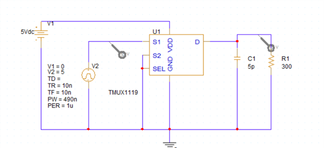

In the figure above, the blue wave represents the input voltage while the green represents the output. The voltage drops over the switch at this load using the Pspice model is 31.8mV. There is also some overshoot at the top of the square wave output (the rise time is 10ns) – this peak is 9.83mV above the input signal on the input rising edge.
Now a look into the different options that may be available for a substitution of the PSPICE file. There are 4 different pathways: a suitable replacement model exists – such as in a TINA library file , simple static RC model of the closed switch,a dynamic RC model of the switch with variable resistance, and a dynamic RC model + leakage currents.
No Pspice Model, but Suitable Replacement Model Exists – Such as a TINA Library
If there isn’t a PSPICE model present, but a TINA-Spice file does exist then the work-around is very straight-forward. For our analog multiplexers and switches, the syntax in the .lib file for TINA and the syntax in the .lib file for Pspice are basically identical and a TINA library can be imported into Pspice or other similar Spice software packages. These models are made the same way – the Pspice model just includes a few other files (mainly for symbols and such) that are not present with the TINA libraries. Please note, however, that the syntax in an HSPICE model .lib file is different from simulators like Pspice and TINA so these cannot be used in place of TINA or a PSPICE model.
Below is the circuit and simulation on TINA:
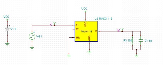
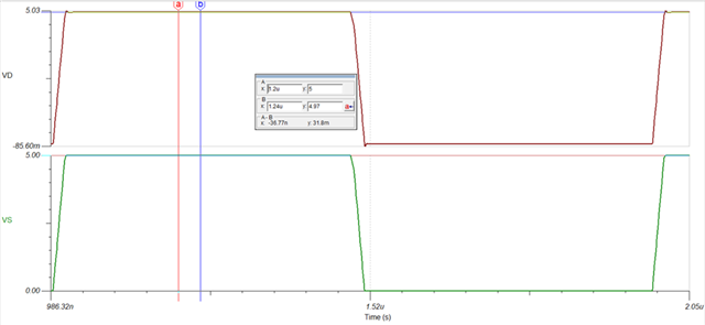
In the figure above, the red wave represents the input voltage while the green represents the output. With the TINA sim there is a 31.8mV drop between the input and output for the 300Ω + 5pF Load. This is the same as the Pspice model results for the same test. The overshoot on the output is rated to ~10mV as the display is limited to 0.01V for the x and y inputs. With this consideration, both the Pspice and TINA models should perform similarly – this is due to them sharing the same library file.
There is No SPICE file available – Generating Simple Static RC Mode
Unfortunately, it isn’t always as easy as just grabbing a similar spice file, as sometimes not even that is included. There is no reason to worry as the multiplexer/switches impact on the signal chain can be approximated well with simple passive models – these come in two flavors, an RC filter, or a CRC filter
RC Filter Passive Switch/Mux Model (Switch Closed)
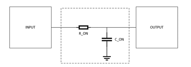
CRC Filter Passive Switch/Mux Model (Switch Closed)
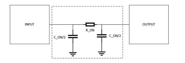
Either of these models can be used. For the simplest form of models, using the typical values can give you a ball-park estimation of how this part will impact the signal chain. For example, let’s use the TMUX1119 and model the closed switch parameters from the datasheet values. Let’s assume a 5V supply voltage at room temperature.
From the datasheet:

With this data, both simple models can be created by using the following values to fill in the model:
- RON = 1.8Ω
- CON = 20pF
- CON/2 = 10pF
Using the same test setup as the previous two simulations a passive model will now be shown:
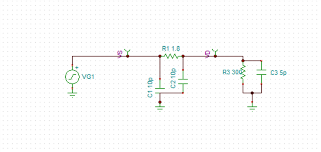
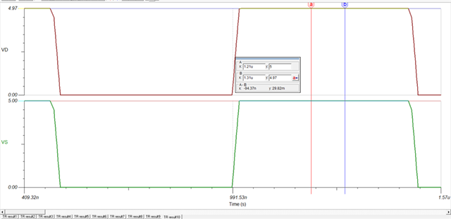
In the figure above, the red wave represents the input voltage while the green represents the output. In this simple model the attenuation at the height of the incoming 1MHz square wave is 29.82mV – this is compared to the TINA and Pspice Sim which gave an attenuation of 31.8mV this gives a little over 6% difference from the TINA and PSPICE model with only the resistance and capacitance modeled. This shows that decent approximations can be made using the passive stand ins.
These simple models can also be used in some boundary condition approximation – this can be done by using the worst-case resistance listed (Worst Case CON is often not spec’d so typical can still be used here). For the TMUX1119 at 5V, that is going to change the RON value to 4.5Ω (for temperatures up to 85°C) and a value of up to 4.9Ω (for temperatures up to 125°C). This isn’t as full featured as a typical Spice model – however higher temperature operating conditions can also be estimated which is typically a feature not modeled within the Pspice libraries of TI’s analog multiplexers and signal switches.
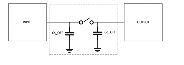
When the switch is open, you can just use a capacitor to ground to show the parasitic capacitance for a switch that isn’t conducting – this is the off capacitance which can be found in the datasheet, as shown below for the TMUX1119.

Some datasheets include a value for both sides for the off capacitance. On some devices, like the TMUX1119, only one side is spec’d. To approximate the “D” side off capacitance take the On Capacitance and subtract the “S” capacitance. So in this case 20pF – 6pF = 14pF. This assumes the internal switch has no capacitance, which isn’t true, but for an approximation this a good place to start as most of the on capacitance is accounted for within the off capacitance.
Simple Model Open Switch
No Spice Model - Creating a Dynamic RC Switch Model with Variable Resistance
In many applications, the simple models will be perfectly acceptable in estimating switch/mux performance, but it does make assumptions that not all applications can handle. One of the largest is that the simple model assumes the on resistance is a constant value – it isn’t, as it varies with supply voltage, temperature, and input voltage. Luckily, this can also be approximated with most of the analog switch/multiplexer portfolio using a simple model. To create a variable resistance in Spice you will need to use controlled sources (1 Voltage-Controlled Voltage Source (VCVS) and 1 Voltage-Controlled Current Source (VCCS)) in place of the static resistor used in the previous model.
Dynamic RC Switch with Variable Resistance Model (Switch Closed)
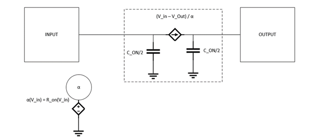
Essentially, it is possible to model the variable resistance as a current using the rearrangement of basic ohms law (V = IR). The current is the input voltage minus the output voltage divided by α which is the on resistance for a given input voltage. This is done using a table in Pspice – the input is checked and a resistance value is given and then that is converted to the current across the switch. To create that table, the on-resistance plots should be used. For this example, the TMUX1119 at 5V will be used.
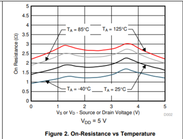
From this graph we can come up with a quick table as shown below (for 25°C):
|
Input Voltage |
Resistance |
|
0V |
1.4Ω |
|
0.5V |
1.6Ω |
|
1V |
1.8Ω |
|
1.5V |
1.8Ω |
|
2V |
1.75Ω |
|
2.5V |
1.8Ω |
|
3V |
1.95Ω |
|
3.5V |
2.25Ω |
|
4V |
2Ω |
|
4.5V |
1.75Ω |
|
5V |
1.6Ω |
Note that these numbers aren’t exact and are just a quick check –this will preserve shape of the resistance curve. If an input voltage is in-between one of the values you chose – the simulator will do a linear interpolation to estimate the value – so the more data points you put the closer to the shape of the graph you will get.
This can be converted into a circuit component with the following library:
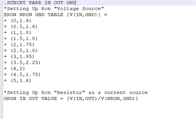
Adding this variability to the resistor gives a better approximation of attenuation at all input voltages from 0V to 5V, which is going to be slightly more accurate than just the average resistance value.
The switch open model will remain the same from the simple model.
No Spice Model – Creating a Dynamic RC Model with Variable Resistance + Leakage Current
Dynamic Model With Leakage Currents (Switch Closed)
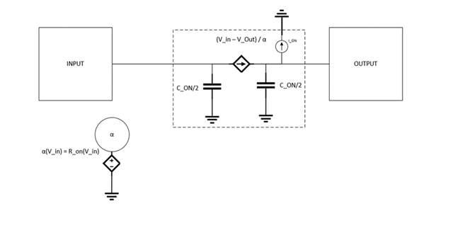
The current source is the typical value from the datasheet – for the TMUX1119 at 5V please see below:

input is 4.5V or 1.5V. If we increase the temperature we can also increase on leakage. For off leakage there is one current source on each input (drain side and source side) with no resistor or current source in the middle.
This model will also help approximate offset errors due to leakage.
Conclusion
In conclusion, there is not a workable spice model for every analog multiplexer/switch. However, the switch parameters can be largely approximated using spice without needing the full model. These simple models can provide estimations for the following parameters: signal attenuation, signal distortion, bandwidth/data-rate, propagation delay, as well as other DC results. For most other AC parameters, a model will be necessary.
Best,
Parker Dodson

