This thread has been locked.

If you have a related question, please click the "Ask a related question" button in the top right corner. The newly created question will be automatically linked to this question.

CD4051B: No output signal

Part Number: CD4051B
Other Parts Discussed in Thread: TMUX7208, TMUX6208

Hello everyone,

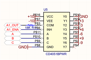
We are using the CD4051BPWR for multiplexing signals of +-3, +-6  and +-9 V, we've checked this values arrive to their respective pins.

The supply voltages are: VCC = 10V, VEE = -10V and VSS = 0V.

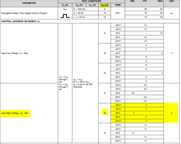
The control signals (A,B,C) are controlled by an ESP32 so their HIGH value is 3.3V, they also change correctly when it's necessary.

The enable pin is connected with a pull down resistor of 10K ohms.

However, we don't see any voltage in the output pin of the device.

I'm attaching a pic of the schematic.

Would appreciate any help or advice,  

Thank you so much.


  • Hi Asier,

    The VIH(min) threshold for VDD = 10V is not 3.3V its 7V. Please see below excerpt from datasheet:

    To have a control pin read a logic high at least 7V is required on the control. pin. For the control pin to read low a voltage of 0V to 3V is required. A voltage of 3.3V puts the switch in an undefined state - but since the 3.3V is very close to the 3V threshold it may still be connected to Y0 which is ground, the device just has a bit more supply current and possibly slightly worse channel performance.

    Also parts such as the TMUX6208 or TMUX7208 have logic thresholds that will work with this application as well as still being able to pass the required voltages as described in this application.

    If you have any other questions please let me know!

    Best,

    Parker Dodson

  • Hi Parker,

    Thanks for your prompt reply, that was defenitely the reason of our issue. 

    We will probably use level converters instead of changing the multiplexer due to space problems ir the PCB.

    But I'd want to know if the enable signal is also considered as an input high/low voltage (it is 3.3V now) and must also be change its level to 7V. 

    Thank you so much,

    Best regards.

  • Yes; as shown above, both address and inhibit pins are control inputs.

  • Hi Asier,

    You are welcome, its no problem! 

    This VIH(MIN) level refers to both the INH and Select (A,B, and C) pins - so all pins have the same logic threshold. However a 7V signal on INH will disable the device and a 3V or less signal on the INH will enable the device as its active low logic (a high signal INHibits the device from making a switch connection) 

    If you have any other questions please let me know!

    Best,

    Parker Dodson