


What is the Off Resistance of an Analog Switch / Multiplexer?
Off resistance of a switch / multiplexer is the resistance seen between a drain and source channel when the device is powered on (VCC = typical supply voltage) and the I/O channel is in High-Z.
The device datasheets do not provide an off-resistance spec, however, this can be calculated using the OFF leakage current spec in the datasheet (IOFF). Note that the powered-off leakage (IPOFF) is different than the OFF leakage current (IOFF). OFF leakage current (IOFF) is the current measured at the input port, when the corresponding channel output is in the OFF state under worst-case I/O conditions. Powered-off leakage current (IPOFF) is the current that leaks into or out of the source pin when power supply voltage VCC = 0 V. This is due to the protection circuitry put in place between VDD and the source, see source for more information.
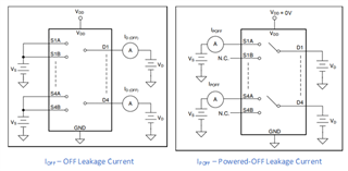
Figure 1. IOFF and IPOFF TMUX1574 Test Setups
In Figure 2 below, IOFF is listed for the TMUX1574 switch. See that OFF leakage current IOFF is tested when VD = 0.8*VDD / 0.2*VDD, and VS = 0.2*VDD / 0.8*VDD, and the switch is off (/EN = HIGH). There is a voltage input present on both the input and output of the switch, but the signal does not pass through the switch since the device is internally disabled. IOFF is then measured either on the drain or source pin through an ammeter in line.
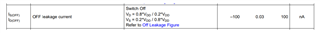
Figure 2. – IOFF Specifications for TMUX1574
With this information, we can calculate the off resistance ROFF using ohms law; V = IR.
Calculation
Worst case off-resistance is when ROFF is at a minimum, since this will represent the smallest magnitude of resistive DC isolation between the I/O of the switch when in the off position. With this in mind, we can follow equation 1 below:
![]()
Equation 1.
The relationship also follows that increase in VDD yields an increase in ROFF.
Example Calculation Using TMUX1574 when VDD = 5.5 V:
ROFF(worst-case) = |V_D – V_S| / |I_OFF(max)| = |0.8*5.5 V – 0.2*5.5 V| / |100nA| = 33MΩ