This thread has been locked.

If you have a related question, please click the "Ask a related question" button in the top right corner. The newly created question will be automatically linked to this question.

TMUX6208: Multiplication of analog signals

Part Number: TMUX6208

Hi Expert,

We need you help for our customer's application. 

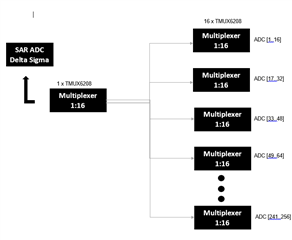
They are currently developing some kind of measurement electronics.. The basic idea is the following: They would like to take a high precision ADC. They would like to multiply the one input of this ADC by some kind of circuit. So that one ADC also becomes n many. Here, the analog multiplexer has caught my eye positively. That would be the TMUX6208 for example. The following specification are in my requirement list:

Input voltage: 0-30V
Analog inputs: 64
Because of this specification I would like to use 9 TMUX6208. I think the type of connection is called cascade connection. Can I connect several analog multiplexers in series? If I could connect multiple multiplexers in series.
How would the behavior change under load ? So I am interested in the edge effects that occur.
If more information is needed, please contact me.

Best regards,

Jonathan

  • The Ron and Con of the mux (in this case, 4 Ω and 180 pF) form a low-pass filter; this results in the bandwidth of 33 MHz. With two muxes in series, you have a stronger filter, and the highest signal frequency will be lower. There will be no other effect.

  • Hi Clemens,
    Good day! Thank you for your response. We do not quite understood why this is so. Assuming our multiplexer, as it was described, consists of a Ron and a Con. When calculating the cutoff frequency I go but as follows for.
    H(s) = R / (sRC + 1)
    fcutoff = 1/(2piRC)
    fcutoff ~ 220 Mhz.
    Where do we have our error. According to what you have said,  a bandwidth of 33MHZ should come out.
    We would be pleased about a short example of calculation?
    Thank you so much
    Best regards,
    Jonathan
  • These are the values listed on the product page.

    This training video uses more complex formulas: 2.4 Bandwidth, crosstalk, off-isolation and THD+noise

  • Hi Jonathan,

    To clarify, did you by any chance mean you want to cascade most of the multiplexers in parallel? In essence 8 muxes connected in parallel cascaded to one. Or are they all being tied in series? In the series case, each time you place a signal switch in the signal path you introduce some signal loss and distortion. The losses and distortion are characterized in the datasheets of our signal switches. Ron and Con are the parameters of significance. The Ron loss will result in lower amplitude of the signal and the Con loss will result in slower rise times of the signal. 

    Cascading multiple devices will introduce losses at each device. To determine if the losses will affect your circuit you need to see if losing the voltage drop created by the 4 ohm Ron at each switch is significant in the application and if you have enough bandwidth margin. Degradation does increase pretty quickly when you start cascading multiplexers. Every instance of the multiplexer is another RC that will affect your bandwidth. Is there a schematic you can provide for the use case? 9 multiplexers in series would likely cause substantial degradation and bandwidth attenuation by the time you reach the 9th mux. With just two cascaded in series, you get twice the insertion loss per cascaded mux. 

    As far as bandwidth is concerned, this is characterized in the datasheet as well (page 20). The true bandwidth (33MHz) differs from "ideal" bandwidth due to various parasitics, external resistance and external capacitance. 

    Thanks!

    Alex

  • Hi Alex, 

    Our cusotmer was able to check your answers and thank you for the support.

    Here is the customer's feedback below. 

     I made a small picture here to explain my use case. On the left side is the ADC(First of all it doesn't matter if it is SAR or Delta Sigma ADC). This has an input which goes to the first stage of the TMUX6208. This first stage allows the multiplexing of the one input to 16 inputs. TMUX6208 multiplexers are connected to these inputs.

    In addition to this, To get a better understanding of the series connection of multiplexers I downloaded the P-Spice model of the TMUX6208. At my first attempts my input corresponded to the output. The input attenuation or insertion loses was zero. Is the input attenuation taken into account in the P-Spice model ?

    Thank you very much for the very generous help so far.

    Best regards,

    Jonathan

  • Hi Jonathan,

    Since the TMUX6208 is a low Ron part and if you're working near DC seeing very little loss is not surprising, but not completely zero loss. May I see the circuit you're using for simulation? I will then work on doing the simulation on our end as well to see what results we get. 

    I am also noticing you said 16 inputs and the ADC [241..256] on the schematic provided. Are you actually needing 17 16:1's or 33 8:1's as opposed to the 9 mentioned in the original post?

    Thanks!

    Alex

  • Hi Alex, 
    Here is the customer's response below. Kindly help once again.
    Customer's response: I  have already sent you a message regarding this. But I already have new knowledge.
    The one about the 16:1 multiplexer, was just to make my point. Actually, it is an 8:1 multiplexer. The electrical edge effects, which were mentioned, probably apply to multiplexers in general.
    I managed to reproduce the input attenuation with the help of the simulation (there was a small error in the simulation).
    I have one last question regarding this.
    To measure a signal correctly, do I need an impedance converter at the input of all 8 ports ? Because according to my current understanding, I load the voltage divider to be measured with the RdsON resistor. Depending on the design whether one or more, correspondingly more or less.  
    Best regards,
    Jonathan
  • Hi Jonathan,

    Glad to see the attenuation was reproducible! I have not heard of needing an impedance converter to measure signals correctly for our switches, so I'm inclined to say one is not needed. Though, I'm a bit confused on the last part of the statement here. Could you clarify what the customer means by the following: "Because according to my current understanding, I load the voltage divider to be measured with the RdsON resistor. Depending on the design whether one or more, correspondingly more or less."

    Thanks!

    Alex

  • Hi Alex,

    Here is the update and example from the customer.

    For example, my measuring point is located between R41 and R42. Here I would connect my multiplexer circuit. If I use two in series, then I would have two RdsOn resistors, i.e. 2 times 4 ohms. Then the signal goes to the further processing. Without the assumption that my signal pickup(ADC/OPV) is high impedance, I would make a parallel circuit of R42 and R43+R44. The current would then divide accordingly and falsify the possible voltage measurement.
    Best regards,
    Jonathan
  • Hi Jonathan,

    Did you happen to have an example that you were wanting to attach here so I can see how their layout looks? 

    Thanks!

    Alex

  • Hi Alex,

    Kindly check. Thank you for waiting.

    Best regards,

    Jonathan

  • Hey Jonathan,

    Without the assumption that my signal pickup(ADC/OPV) is high impedance

    After reviewing what we have discussed so far, may I ask why we are not making the assumption that the ADC input is high impedance? Typically it is the case that ADC inputs are high impedance so just curious. If we go with the fact that there is a high impedance input, then no impedance converters are necessary here. 

    Thanks!

    Alex