This thread has been locked.

If you have a related question, please click the "Ask a related question" button in the top right corner. The newly created question will be automatically linked to this question.

TMUX1574: Use 2 TMUX1574s for a Quad-SPI

Part Number: TMUX1574
Other Parts Discussed in Thread: TMUX646, TS3A27518E

Hi there,

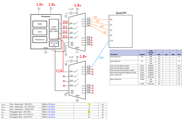
The picture below shows an application of the TMUX1574 for a Quad-SPI.

According to the datasheets of the MUX and the Quad-SPI, it seems 2 MUXs can work together.

Setup Time and Hold Time of the Quad-SPI are "ns" level.

The delays from MUXs are "ps" level.

We use one MUX for 4 Data, and the other for CLK only.

SEL pin is at a static level. (no change on SEL pin)

But somehow the design is not working currently.

May I know if this design makes sense from your experience?

Thank you so much for your replies in advance.

  • Yes, such a design makes sense.

    "Not working" does not really tell us anything.
    Does it work if you bypass the switch? Can you show oscilloscope traces from both sides of the switch?

  • Hi Clemens,

    Thank you for your reply.

    May I know if separating CLK and Data into 2 different MUXs is a common way to do?

    We will work on that, to get some waveforms with and without the switch.

    However, one of my colleague mentioned that it is not worth to capture any waveforms because the design is totally wrong.

    So I am here to check if this design is not common...

    Thank you for your help!

  • Using two muxes is fine as long as you have enough time (tTRAN) between changing SEL and the SPI transfers.

    There is nothing obviously wrong in the picture, but it is not very detailed. What exactly is "totally wrong"?

  • Hi Clemens,

    Yes, I am pretty sure that tTRAN is good enough in this applications.

    (SEL is a static value.)

    My colleague mentioned that "he doesn't see any designs like this, all the data should go along with CLK, you use 2 muxes, that is totally wrong".

    In order to persuade him to work on the debugging, I have no option but to seek the helps from you. (The board is on his side.)

    It definitely has something wrong with this circuit, maybe layout causes some propagation delays(?), but at least we know that it is worth to work on the debugging...

    Thank you Clemens!

  • Possible problems could be that the two SELs are different (not in your case), or that the electrical characteristics of the two muxes are too different (but in your case, the worst-case min/max difference should OK).

    What is the signal frequency?

    Oscilloscope traces would show problems with bandwidth or skew.

    It might be possible to use a mux with more channels, e.g., TMUX646 (BGA) or TS3A27518E (much lower bandwidth). But I am not at all sure that this would improve the situation.

  • Hey Holton,
    This should definitely be feasible. The switch is just a passive device so it's similar to adding some resistance and capacitance on the trace. The timing specs will of course skew a tiny bit but the TMUX1574 there really shouldn't be much of a effect here. Seeing as you're also passing the clock through another 1574, the effects would be roughly the same on the clock vs the other data traces. The clock signal wouldn't know if it's in the same mux or a different mux. It would just observe the parasitics on the channel it's on and the specs will all remain within the datasheet specs so this should be just fine.

    Do the traces all have the same length? The only other thing I can think of is that the clock is being routed in such a way that it's adding skews the timing too much.

    Otherwise, we'll need some oscilloscopes shots of what is actually being seen as wrong.
    That being said, from the quote you sent,

    "he doesn't see any designs like this, all the data should go along with CLK, you use 2 muxes, that is totally wrong".

    it almost sounds like your colleague just doesn't believe it will work but has this actually been tested yet?

    Thanks,
    Rami

  • Thank you Clemens.

    After checking the waveforms, we found that the waveforms are almost the same with and without the MUX.

    Means the problem is not from the MUX, even not related to the SPI link.

    We found that the problem is from JTAG link, after we adjusted the data rate of the JTAG link, we are able to program the SPI now.

    Thank you so much for your help!

    And thank you for your suggestions for more channels.

  • Thank you Rami for helping me clarify the problem.

    The traces are all matched, and we found the problem is from JTAG link.

    Thank you for your reply and Clemens's reply, so that I can persuade my colleague to work on the waveforms capture.Grin

  • Hey Holton, glad to hear it worked out!
    If any other questions or concerns come up, don't hesitate to reach back.

    Thanks!
    Rami