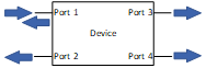
S-parameter (or scatter parameter) models are AC based models used to understand small scale AC performance of devices. They are created by measuring the scattering (reflections and transmissions) of a device based on some stimulus (see the diagram below). A stimulus is sent to port 1, and all ports (including the reflection on port 1) are measured at multiple frequencies. This is then repeated for all other channels resulting in a matrix, which is saved as the s-parameter model, and can be used with other models to see a whole system performance.
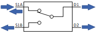
For example, lets use the TMUX1574. Say we connect the 4 ports to channels S1A, S1B, D1, and D2 respectively. Here we can start to see how to get some useful measurements from the s-parameter model. If we have a stimulus on S1A, and measure the result on D1, this would be the bandwidth of the device, or the loss across the switch when ON. By convention, this measurement would be called S13. Meaning the scatter parameter where port 1 is the stimulus and port 3 is measured.
Additionally if we put a stimulus on S1B and measure the result on D1, this would be off-isolation, or the isolation across the switch when OFF. This would be S23
If we put in a RC model of the switch we can see more details on how the switches are affecting the AC signals. Reminder, all of TI analog switches are bidirectional, so the bandwidth from S1A to D1 is the same as D1 to S1A (S14 = S41).
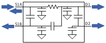
- Bandwidth (S13, S31): The resistance from S1A to D1 is the on-resistance, which with the capacitance on the source and drain pins, creates a low pass RC which limits the frequency response.
- Off-isolation (S23, S32): The capacitor from S1B to D1 creates a high pass filter which blocks the low frequencies, but allows the high frequencies to pass through.
- Crosstalk (S12, S21, S34, S43, S14, S41, S24, S42): The capacitors from S1A to S1B and from D1 to D2 also create a high pass filter.
- Con/Coff (S11, S22, S33, S44): the on/off capacitance of each pin is simply the capacitance with respect to ground. This can be evaluated in the s-parameter by putting a stimulus on a channel and measuring the reflections back on that same channel.
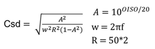
Overall S-parameter models are extremely useful for AC simulation, but don’t provide much insight to DC, and can’t support transient like state switching. If a S-parameter model is not available for a TI MUX, capacitors and resistors can be selected based on datasheet values, and a passive RC model like the one above can be used to give approximate performance. The equation to calculate the capacitors for off-isolation and crosstalk is below, assuming a 50 ohm load.