Because of the holidays, TI E2E™ design support forum responses will be delayed from Dec. 25 through Jan. 2. Thank you for your patience.

This thread has been locked.

If you have a related question, please click the "Ask a related question" button in the top right corner. The newly created question will be automatically linked to this question.

CD4052B: AHD camera multiplexing

Part Number: CD4052B
Other Parts Discussed in Thread: CD4053B, CD4051B, SN74LV4052A, CD74HC4052

Hi,

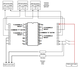
I am trying to use the CD4052B as a video multiplexer for AHD cameras. I am using X a Y to connect the coax core and shield. The idea is to thave a single output on the common X and Y and two cameras on channel 0 and channel 1 respectively and to be able to switch between cameras. To address A and B I use a rocker switch in order to have A high/B low or B high/A low or in neutral position Alou/Blow. Please see below my wiring drawing for info. The issue I have is that when switching the rocker switch I am not getting any video output. Initially I had the cameras on channels 1 and 2 so I tried to simply it in terms of addressing by putting a camera on Channel0 (A=0,B=0) and a camera on channel 1 (A=1,B=0). So with the camera on Ch0 I am getting a very noisy and instable video however, when swithing the rocker switch on poition to have A high, I do not get anything  out. To add to this when coming back to A low Ch0 is not outputting anyhting. I have tried a 5V input and 10V input to see if it would change anything, but no difference. I am not an electronic guy so it is an quite unknown territory. I must have missed somehting butcannot figure out what, Any idea? Thank you!
  • Hey Damien,

    I'm not very familiar with video signals and how they look. Do you happen to know the frequency and voltage of the signals you're working with? 

    I'm not seeing anything that stands out as a issue here though on the mux side. What kind of board/setup are you putting this one? And do you have access to an oscilloscope or even a multimeter so we can double check the voltages going on the control and supply pins during each toggle of the switches?
    If you have an oscilloscope I'd like to see the waveforms before and after the mux, then if we can remove the mux, and blue wire the path from the COAX output to camera 0 (or 1, your pick) we can rule out if the board or setup itself is causing any troubles. 
    You could probably get away with not using an oscope here as well and just see if the video works when you blue wire around the mux.

    I think I follow for the most part what you're trying to do but could you possibly share the states that you have your A and B in relative to the output seen? Would help me better organize the conditions and their behavior. 

    Thanks!
    Rami

  • What supplies are you using? What voltages and frequencies do you want to switch?

    (CD4000 devices are very old and have lousy characteristics at low voltages. You probably need a different switch)

  • Hello Rami,

    Thank you for replying.

    Will try to get the info Thursday when in the lab if enough time.

    The board is made up from a prototyping pcb, so wires and solder. Although it's ugly it is relatively straight forward. I have tested the camera individually and they are working fine. Things gets complicated when the MUX gets involved.

    Regarding the states of A and B. When rocker switch is in a neutral position A=0 and B=0  and Ch0 is live. When rocker switch closes the loop on A, A=1 and B=0, this gives ch1 live. switch closed on B, A=0  and B=1 ch2 is live.

    Am I right to understand that the switch needs to be continually close on A to have A=1 or should it be a pulse only (same for B)?

    Thanks!

    Damien.

  • Hello Clemens,

    Thank you for helping.

    Not sure I understand correctly. Since it is a prototype, I am using a workbench power supply to power the MUX, 5V on the positive and negative back to the power supply. I have tried 10V too. The cameras are powered separately with 3.3V from a separate channel on the power supply.

    Not looking to do any high frequency switching. I am looking to purely manually switch from one camera to another when needed. A and B are on the same power line i.e 5V in my case when the switch is activated. When switch in neutral position, A and B should be pulled down via the resistors.

    I went for this model of chip because of the X-Y channels, I thougth it would be nice to connect some coax to it to switch between cameras but with a reduced number of coax.

    Thanks.

    Damien

  • Sorry, I was asking about the characteristics of the video signals.

  • Hey Damien,

    Am I right to understand that the switch needs to be continually close on A to have A=1 or should it be a pulse only (same for B)?

    Yes, you'll need to maintain the state for the logic to hold. There won't be anything that latches the state in. 

    Clemens does make a good point here though that the performance at the lower rails isn't the greatest so a lower voltage switch may do you better. Although you did also mention that you went up to 10V as well and saw similar behavior. But if you wanted you could try the SN74LV4052 which would be a drop-in replacement with better characteristics at lower voltage.

    That being said, I'll await your lab tests in the meantime

    Thanks,
    Rami 

  • Hi Rami and Clemens,

    Regarding the state of A and B this is what I understood as well, so am ok here with my switch setup.

    I now understand what you meant Clemens, hence I tried with 10V rather than 5V. However, I must admit I am not to sure to understand properly p14 of the tech spec. quote below.

    "The CD4051B, CD4052B, and CD4053B analog multiplexers are digitally-controlled analog switches having low
    ON impedance and very low OFF leakage current. Control of analog signals up to 20 VP-P can be achieved by
    digital signal amplitudes of 4.5 V to 20 V (if VDD – VSS = 3 V, a VDD – VEE of up to 13 V can be controlled; for
    VDD – VEE level differences above 13 V, a VDD – VSS of at least 4.5 V is required). For example, if VDD = +4.5
    V, VSS = 0 V, and VEE = –13.5 V, analog signals from –13.5 V to +4.5 V can be controlled by digital inputs of 0
    V to 5 V. These multiplexer circuits dissipate extremely low quiescent power over the full VDD – VSS and VDD –
    VEE supply-voltage ranges, independent of the logic state of the control signals. When a logic 1 is present at the
    inhibit input terminal, all channels are off."

    I have VDD=5V, VSS=0V but my VEE is also 0V. In the example above from the tech spec, it seems that there is 18V range of control. So in my case I would have only 5V range controlled by digital input of 5V. If my video signal is very low, which I havent measured yet but I would expect to be the case, I am basically putting myself potentially beyond what the chip can achieve.

    I like the idea of the SN74LV4052 you suggested Rami. That woul make more sense since I am using rather  low voltages. I could even power the cameras from the feed line.

    I will do the measurements tomorrow.

    Thank you both.

    Damien.

  • now understand what you meant Clemens, hence I tried with 10V rather than 5V. However, I must admit I am not to sure to understand properly p14 of the tech spec. quote below.

    "The CD4051B, CD4052B, and CD4053B analog multiplexers are digitally-controlled analog switches having low
    ON impedance and very low OFF leakage current. Control of analog signals up to 20 VP-P can be achieved by
    digital signal amplitudes of 4.5 V to 20 V (if VDD – VSS = 3 V, a VDD – VEE of up to 13 V can be controlled; for
    VDD – VEE level differences above 13 V, a VDD – VSS of at least 4.5 V is required). For example, if VDD = +4.5
    V, VSS = 0 V, and VEE = –13.5 V, analog signals from –13.5 V to +4.5 V can be controlled by digital inputs of 0
    V to 5 V. These multiplexer circuits dissipate extremely low quiescent power over the full VDD – VSS and VDD –
    VEE supply-voltage ranges, independent of the logic state of the control signals. When a logic 1 is present at the
    inhibit input terminal, all channels are off."


    In the meantime, I just want to take a stab at this as well because quite frankly I am not a fan of how this is written and it's very confusing. 
    I believe all this paragraph is trying to say is that the signal you have on the analog inputs can span between the positive supply (VDD) and the negative supply (VEE) or VSS/GND if VEE = VSS. 

    I believe it's also trying to say that your lowest max VIH for your 'logic 1' is 4.5V since the supply has to be at minimum 4.5V. 

    This is another reason why these old devices aren't always the greatest. For the specific supply test conditions in the datasheet they're specified well but they aren't very explicit in the upper and lower boundaries and the datasheets were created nearly 30 years ago so sometimes we can't really dig into what exactly they were trying to get across, as we see in this paragraph.

    If you do move to and try the SN74LV4052A, you'll atleast see more clear specs Sweat smile

    Thanks,
    Rami

  • Hi Rami and Clemens,

    Managed to hook a camera to the oscilloscope. Only had little time so this is what I managed to grab:

    camera output no MUX :

    Vpp=173.3mV

    signal freq=96.15Hz

    signal period=10.40 micro second

    camera output after MUX channel 0:

    Vpp=215mV

    signal freq=15.72Hz

    signal period=63.6 micro second

    Some serious discrepencies here and not sure where they are from. I woul take away the fact that the signal is low voltage and that could be the issue with the chip.

    Thanks,

    Damien

  • Do you think the signal frequency could be limited by the switching frequency of the chip itself?

  • Hey Damien,

    That's very interesting that the frequency decreased 6x the original but the Vpp increased. How did you measure these? Even if the mux couldn't handle it, I wouldn't expect it to decrease the frequency itself. Unless you're not looking at the waveforms and you're just pulling the data from some other device somehow? Then maybe it isn't registering some of the peaks for some reason.
    Same with the Vpp increase. If the Bandwidth was the issue, I wouldn't really expect the Vpp to increase. But there could be some reflections and spiking that is being measured as a higher peak. So back to the first question of how you got this data and were you able to physically look at the waveforms? 
    But I do agree, serious discrepancies there. And perhaps a the LV4052A could help but it's still not clear what the CD4052B's limitations actually are here.

    When you say switching frequency, do you mean the toggling speed on the control pins? What's the speed you're switching at? It could be a possibility and would be pretty easy to check by simply biasing the controls pins to a high or low state and holding them there for an extended period of time and seeing the results

    Thanks,
    Rami

  • From what information I've been able to find, AHD is just standard composite video with higher frequencies, typically 40 MHz, depending on the resolution.

    I suspect that your oscilloscope triggered on the vertical/horizontal blanking intervals.

    Video cables have a characteristic impedance of 75 Ω; I'd estimate that the resistance of CD4000 switches is too large. The CD74HC4052 should work much better.

    (Does your video signal use negative voltages?)

  • Hi Rami,

    Only managed to get  photos with my phone and wasn't too sure if they would be useful.I realise I could have saved some screen shots, tried to be quick. The first photo is without the mux, the oscillsope clamped on the camera directly (i.e. chan1 of oscillo on the video wire and oscillo ground on the ground of the camera which is also the ground of the power suplly) and powered by an external power supply and the video the signal goes directly to a screen via a dvr. The second photo, the camera is attached to the same power supply but the video signal, this time is going through the MUX via channels x0 and y0 and then to the dvr and screen. Since it is on x0 and y0,  A=0 and B=0. I don't think I have taken the right time to get the exact same scale, but the waveforms are visible.

    Regarding the frequency, sorry I was looking at the section 6.6 and 6.7 before realising it was for an AC charactiristics.

    Visually, the video quality is very degraded, almost like I am not getting the full signal. I went through x0 and y0 to remove the A and B parameters, so in effect the video signal should follow a straight path from x0,y0 to xcom and ycom.

  • Hi Clemens,

    you might be right, I will redo the measurements to make sure that I have set the oscillo properly. Also sometimes, I wonder if the camera is a true AHD in terms of frequency carrier, definitely in terms of number of pixels on the sensor resolution. I wouldn't be surpirsed that we could find ourselves in the low spectrum of the MHz. I have a more expensive industrial AHD camera but I am a bi reluctant at that point to connect it until I know exactly what is going on with the circuit :-)

    The video signal negative part is usually coupled to the negative of the power supply. At some point on those small cameras there is a bridge to connect the shield of the coax to the negative of the power supply, which is good to remove noises from the source. If the bridge is not made on the board it can be done at the junction to the coax.

    I will have a look at the CD74HC4052.

    Thanks a lot again both of you for taking the time to think about my issue, very much aprreciated.

    Going back on Saturday, so I shall be able to hook the system again.

    Damien.

    PS: Now thinking about it, I am realising that I have made a mistake when clamping the oscilloscope, I left it at the same place right after the cameras wires which was ok without the mux not good anymore with the mux. I should have clamped on the common output...sorry about that.

  • Hi Clemens and Rami,

    Got some new results but I am not too sure about my setup on the oscilloscope. I have set the oscillo recieved signal to video 1080p/30fps. The camera is a cheap thing and not much info are available. It is indicated 1080p NTSC so I am asusming a 30fps.

    Added a some averaging (256) to clean up the signal and tried to open a mearuring range to characterise the signal in two ways. The signal looks like packets of data being carried which I believe would make sense since we have got a number of frame per seconds. So I tried to have the measuring window over several packets and the frequency on top of a packet.

    Photos below.

    In summary I have:

    no mux:

    packet freq=15.62kHz, Vpp=136mV

    signal freq=169.5kHz, Vpp=98mV

    After mux:

    packet freq=15.87kHz, Vpp=28mV

    signal freq=92.59kHz, Vpp=34mV

    I am not sure if I am measuring the right things here and the right way. The packets freq is consistant, the signal frequency varies a lot. The voltage is significantly reduced which would tie up with what has been suggested regarding the too high internal impedance of the chip possibly?

    I think I am reaching my limits in terms what could be measured I am afraid. I might try the two chip that have been suggested the CD74HC4052 and the SN74LV4052A, not sure yet about the differences, I will have to read the specifications and try to understand.

    NO MUX DATA:

    Over several packets:

    over signal:

    AFTER MUX:

    Over several packets:

    Over signal:

  • Forgot to mention that after the mux, the signal on the oscilloscope is intermitent. By this I mean that the waveform come and goes almost like it is on and off. Tried to upload a video but it didn't work.

    Thanks,

    Damien.

  • Hi Damien,

    Rami is out until Thursday and as he's been pretty involved in this topic can this wait until he's back?

    Regards,

    Alex

  • Hi Alex,

    No worries at all.

    Thank you for let me know.

    Regards,

    Damien.