Other Parts Discussed in Thread: TMUX7412, TMUX6212, TMUX6202, , TMUX6201
Dear TI Engineer:
We have purchased some products from your company and encountered two issues during use, which are inconsistent with the manual description.
Question 1:
TMUX7412 IC,The circuit design using this chip did not match the description in the manual (as shown in Figure 1) during actual testing.
TMUX7412 test conditions:VDD=+5V,VSS=-5V,SEL1=3.3V,S1=+5V,D1 connected to 1K resistor to ground.
TMUX7412 test result:The D1 terminal can only measure a voltage of 3.9V; When VDD is increased to 6V and S1 is increased to+6V, a voltage of 4.9V is measured at the D1 end, which means that there is a voltage difference of about 1.1V between the output end and the VDD power supply voltage. However, the manual describes the voltage between VSS and VDD as: VSS~VDD.
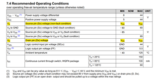
图1 TMUX7412 recommended operating conditions
Comparative testing: TMUX6212 chip was also used in the product design, and the voltage range described in the chip manual for VS and VD is consistent, ranging from VSS to VDD.
TMUX6212 test conditions: VDD=+5V, VS=-5V, SEL1=3.3V, S1=+5V, D1 connected to 1K resistor to ground.
TMUX6212 test result: A voltage of 5V can be measured at the D1 end. When VDD is applied to+6V and S1 is applied to+6V, a voltage of 6V is measured at the D1 end. The chip is consistent with the description in the manual (as shown in Figure 2).
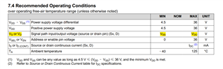
图2 TMUX7412 recommended operating conditions
I would like to know if the issue that occurred is due to the TMUX7412 chip manual not describing a pressure difference of around 1.1V, or is there an abnormality in the purchased product, or is there an issue with my testing method?
Question 2:
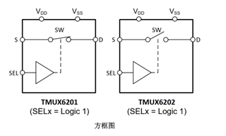
In actual testing of the TMUX6202 chip, the switch closed when SEL=1, which does not match the manual description. I would like to know if it is a problem with the purchased product or the manual description?
Best Regards