This thread has been locked.

If you have a related question, please click the "Ask a related question" button in the top right corner. The newly created question will be automatically linked to this question.

TMUX7234: Design for review (RS232 Crossover)

Part Number: TMUX7234
Other Parts Discussed in Thread: TMUX4827, MAX3221

Tool/software:

Hello,

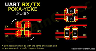
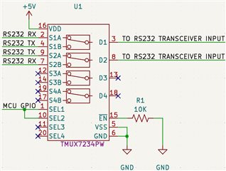
    I have been researching how to swap RS232 RX and TX connections and found the image below.  It would work but should the user need to change the connections they would have to remove and re-solder the resistors.  During my research I saw someone recommend the ADG5434.  While it seems the ADG5434 would work, it requires a 9V supply and I only have 5V available.  This constraint lead me to the TMUX734.  I have attached a schematic if someone would be willing to review it.

    The two questions I have are:

  1. Is the TMUX7234 suitable for switching true RS232 voltages?
  2. Can the TMUX7234 operate as required, to switch RS232 voltages, with only a +5V supply as shown in the schematic?

    Thank you for your time.

  • With a 5 V supply, the TMUX7234 can switch only 0 V … 5 V signals.

    You would need a switch like the TMUX4827, but ±12 V might not be enough for all RS-232 buses. (Most RS-232 drivers do not actually go beyond ±6 V. but there are ±15 V ones.)

  • While this isn't related to the TMUX7234, another option I've seen recommended is to use multiple transceivers that have a shutdown pin like the following image.  It also mentions the transceiver having tri-state outputs.  Does the TI MAX3221 have tri-state outputs?  I searched the datasheet but found nothing that says if it does or does not.  Unless that is what the slashes in the block diagram on page 1 of the datasheet indicate.

  • You could pull /FORCEOFF low and /EN high to disable all outputs, but this would not remove the 5 kΩ input resistor.

  • Hi Billy,

    It looks like your question about TMUX7234 has been answered. Please let me know if you have any other questions here. If you have additional questions about the MAX3221 then I can move this thread to the appropriate product line. 

    Regards,

    Alex

  • The only question I would have is, what would having two 5k resistors connected as Clemens mentioned cause any issues?

  • The 5k resistors to GND are part of the RIN circuitry of the MAX3221. Normally the outputs would swing +5V or -5V (some RS232 devices can be higher) but if they were to be disabled (tri-state) then the RS232 transceiver's input would see an invalid input voltage (between -0.3V and +0.3V because it would likely go to GND state). Table 8-1 (the last 2 columns) state if FORCEON is low and FORCEOFF is high then the device would enter the automatic power down feature. You don't have to worry about this if the FORCEON and FORCEOFF pins are biased to a high state though since the auto power down feature is disabled in this set up.

    -Bobby

  • A load of two receivers = 2.5 kΩ is higher than expected by a RS-232 driver. The output voltage might drop too much; in any case, you lose noise margin.

  • Billy,

    I might need a clearer picture of what the overall system looks like. Can you draw a block diagram of the RS232 system? 

    From what I can see, I don't think you would have 2 receivers in parallel with another RS-232 driver connected like what Clemen's post seems to be pointing to. I suspect I may be misunderstanding something. I'm also assuming the schematic from your first post is showing the RS232 lines on both sides of the switch and not the TTL that would go into/out-of the RS232 transceivers.

    -Bobby

  • Bobby,

    The attached image isn't exactly a block diagram, but I hope it will clear up any confusion.  You are correct, the TMUX7234 has only RS232 signals connected, no TTL.  I am only looking at reversing the RS232 lines while the TTL will always be connected to the same MCU pins.

  • It took me way longer than I care to admit to figure out this out but I think I got it now. 

    Clemen's assessment is correct. You will have a set up where 2x RS232 inputs would be tied together (basically 5k resistors to GND in parallel). Whatever RS-232 driver is connected to this will end up seeing a heavier load. Worst case scenario is your output voltage on the driver may drop from it's typical values (+/-5.5V typical for the MAX3221 device for example) to whatever Vcc value you use (so 3.3V in worst case) if the cable is very long (capacitive load) with a fast datarate this could lower the output swing even more. Lower cable distance and slower datarate would likely get you closer to Vcc in the better scenario.

    -Bobby

  • Bobby/Clemens,

    In that case, I think I will find an alternative approach.  Maybe stick with a 2X2 jumper or explore using a DPDT latching relay.  Thank you for providing such detailed explanations in your responses.