Tool/software:
I plan to use a comparator to determine the signal amplitude and accordingly either reduce the signal by a factor of 1/10 or allow it to pass through unchanged.
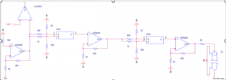
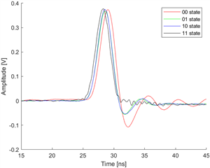
The circuit I'm designing is shown in the diagram below. However, when configured this way, there is a timing issue as shown in the second diagram.
The circuit below repeats the same structure twice. The 00 state indicates no attenuation, the 01 state indicates attenuation once in the first circuit, the 10 state indicates attenuation once in the second circuit, and the 11 state indicates attenuation twice.
I believe the cause is the capacitance of the switch. Do you have any suggestions for modifications to resolve this?