Because of the holidays, TI E2E™ design support forum responses will be delayed from Dec. 25 through Jan. 2. Thank you for your patience.

This thread has been locked.

If you have a related question, please click the "Ask a related question" button in the top right corner. The newly created question will be automatically linked to this question.

TMUX1574: Select pin and package

Part Number: TMUX1574
Other Parts Discussed in Thread: SN3257-Q1

Tool/software:

Hi,

1. Based on datasheet, SEL pin has weak 6Mohm PD and SxA is connected to Dx pins by default. Can we add external 10k pull down resistors on SEL pin to ensure SxA only gets set as default after every power cycle?

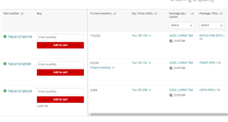
2. UQFN package is the smallest in this family and seems to have better performance overall. But this is still cheaper than TSSOP and SOT-23. Why is that?

  • Hello Nandini,

    The TMUX1574 has powered off protection, meaning the I/Os of the device are in high impedance mode when the supply is 0V. I am not sure exactly where you found that SxA is connected to Dx pins by default. 

    Also, the UQFN is actually the most expensive package we offer. Where did you see it was the cheapest? 

    Thanks,

    Nir 

  • Hi Nir,

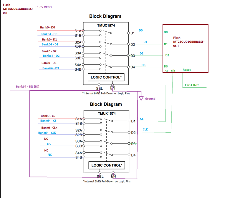
    Let me rephrase my first question.. I have an usecase where 2 hosts will be connected to SxA and SxB and slave flash will be connected to Dx. After every power cycle, I want SxA pin to be connected to Dx by default. The master will toggle select pin based on need to connect Dx to SxB. How can we achieve this? 

    Reg the 2nd, I Checked the price on Digikey. Now the TI pricing makes more sense.

  • Hello Nandini,

    Understood, thank you for clarifying. Your use case is for an active low mux that maintains a closed signal path after a power cycle.

    The TMUX1574 is an active high device, so it can't accomplish such behavior. This is an internal design within the mux, it can't be accomplished with external components combined with our multiplexers. 

    I can recommend the SN3257-Q1 instead. It is an active low device that will fit your application. 

    Thanks,

    Nir 

  • Hi Nir,

    I need some more clarity on why TMUX1574 can't work. 

    Here is what I find in the datasheet:

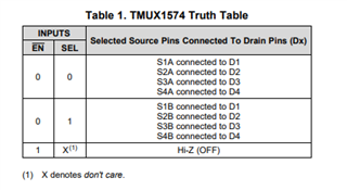
    • Per truth table 1, when Enable is 0, SEL pin controls the signal path.
    • Per Device Functional Modes section, SEL pin is internally Pulled down with 6Mohms and hence device powers-on in a known state.  (We can add external strong pull down resistors in parallel to 6M if needed to make SEL pulled down strongly to set it to SEL 0)
    • Per Device Functional Modes section, Enable is active low - I am not sure why you are saying it is active high. (We will keep it tied to the ground to ensure it is always active.)

    If we do these (SEL - 0 and EN - 0), the device will power on in a known state ( Dx connected to SxA). Is there anything I am missing here?

    WRT SN3257-Q1, I find similar information. I am not sure why this is suggested over TMUX1574. Can you pls share more details?

    Thanks. 

  • Hello Nandi,

    I apologize for the confusion, I got it mixed up please ignore the SN3257-Q1 recommendation. The TMUX1574 is an enable low device you are correct. 

    Yes, as you mentioned pulling EN low, turns on the SEL pin. If you also pull down SEL you will turn on the A channel and close the SxA to Dx switches as per the truth table below. 

    Yes, you can tie a PD resistor in parallel to ground to guarantee SEL will turn A channel on.

    Again, I apologize for the mix up.

    Thanks,

    Nir 

  • Thanks for confirming Nir.

    We will go ahead with TMUX1574 SOT-23-THIN package. Hope it won't have any issue to support about 125MHz SPI data rate.

    Master will drive the SEL pin at 1.8V when the switch needs to be toggled. Will an external SEL pin Pull down of 100K be ok in that case? 

  • Hello Nandini,

    The TMUX1574 has a rated bandwidth of 2GHz. It should reliably work in a 125MHz SPI data rate application. 

     I suggest starting with 100k first and testing if the PD is strong enough. It might require multiple tests with different resistor values. 

    Thanks,

    Nir