


Tool/software:
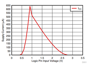
Shoot-through current occurs when CMOS inputs are somewhere between their High and Low voltages, effectively turning on both MOSFETs in the CMOS structure. In many devices, including analog multiplexers, this creates a low impedance path from the supply to ground. This will increase the overall power consumption of the device and system which could even lead to damaging the device. In a multiplexer, this shoot-through current occurs on the control pins. These may be called SELx, Ax, EN, OE/, etc. The figure below shows a simple CMOS buffer that is commonly present internally on the control pins of muxes and other devices with digital inputs. The red arrow highlights the path where the shoot-through occurs. Note from the graph on the right how the current spikes as the logic pin input voltage is between the rails.

Most CMOS devices will have some shoot-through current but there are some ways to minimize this current.
- Keep logic at the rails and avoid slow logic transitions
When toggling the control pins on the multiplexer, the less time the control inputs spends between VIH and VIL (FAQ on VIH/VIL) the better. When the input stays between these ranges the low impedance path shown in figure 1 will turn on and shoot-through current will occur. Ensuring that the logic happens at the rail (positive supply and ground***) and doesn’t slowly linger between VIH and VIL will help minimize the shoot-through current.
***For dual supply devices, the logic is referenced to ground, NOT your negative supply (VSS), so the lower rail will be ground for your logic low. - Selecting a mux that is designed to minimize the shoot-through spike
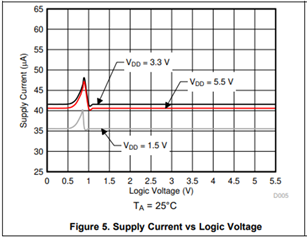
While you can’t completely avoid shoot-through current, selecting a mux that is specially designed to minimize the effects, like the TMUX15xx family and TMUX72xx family, can help reduce the impact. Often these devices will have 1.8V logic compatible inputs. These will have smaller hysteresis ranges (difference between VIH and VIL) with reduced shoot through current. The 1.8-V Logic for Multiplexers and Signal Switches goes in further detail on this and offers more recommended devices. Below is an example of the shoot through current spike for the TMUX1574. Note how the range where the spike occurs is minimized and the peak of the spike is also minimized too.
| 1.8V logic compatible devices with minimized shoot-through current | |||
|
Device |
Configuration |
Key Features |
1.8V logic compatible |
|
4ch 2:1 |
Powered-off protection, 2GHz BW |
Yes |
|
|
4ch 1:1 |
Powered-off protection, 3GHz BW |
Yes |
|
|
1ch 1:1 |
44-V latch-up immune, low leakage |
Yes |
|
|
4ch 1:1 |
44-V latch-up immune, low leakage |
Yes |
|
|
8ch 1:1 , 2ch 4:1 , 2ch 3:1 |
±12-V signal range |
Yes |
|