


Other Parts Discussed in Thread: TLV61047
Tool/software:
Bug in the 5V → 16V PWM Booster Controller
Context
During thermal chamber tests, it was observed that when ambient temperature reaches 65 °C, the analog I/O system stops operating.
To isolate the cause, the step-up converter (U10) was powered individually with an external +5 V source. The +16 V output was disconnected from the system and connected to an external resistive load equivalent to the nominal current consumption of the components usually powered by this rail.

Peripheral components in the circuit:
- Inductor: L3 – ELL-6SH100M
- Diode: D8 – MA22D2800L
- Capacitor: C52 – GRM21BR61E106KA73L
Initial conclusion
The currently used PN (MIC2288) seems to be either undersized or behaving incorrectly at temperatures above 65 °C.
Alternatives tested
Different PNs were evaluated as possible replacements for U10. However, all tested devices showed the same problem:
|
Manufacturer |
PN |
Junction Temp (datasheet) |
Result @25 °C |
Result @65–70 °C |
|
Texas Instruments |
LM27313XMFX/NOPB |
-40 °C to 125 °C |
120 mA (step-up), 19 mA (3V3 + detector) |
After 20 min: step-up 195 mA → failure |
|
Microchip |
MIC2619YD6-TR |
-40 °C to 125 °C |
128 mA (step-up), 19 mA (3V3 + detector) |
After 10 min: step-up 133 mA → failure |
Additional investigations :
Peripheral components: the EVK was checked and compared with the datasheet; all peripheral components, inductor, diode, and capacitors are as recommended.
10 nF capacitor in the feedback line: there was doubt as to whether it could be delaying the response at high temperatures. The capacitor was removed, but the problem persisted.
Switching frequency: analyses on the bench and in the datasheet confirmed that the frequency does not vary with temperature or load. Measurement: 1.5 MHz.
Influence of the inductor (L3): The inductor was changed and the same test was performed (22uH and 4.7uH), checking not only the behavior and currents involved in the system, but also the switching waveform of the 16V signal, and the conclusion is that the inductor has no influence on the undesirable behavior at high temperatures.
Influence of the capacitor (C54): The capacitor was changed and the same test was performed (22uF), checking not only the behavior and currents involved in the system, but also the waveform of the 16V signal switching, and the conclusion is that the capacitor has no influence on the undesirable behavior with temperature.
Targeted bench test
The circuit was completely isolated:
- External +5 V source at the input.
- Resistive load at the output.
- Step-up removed from the entire main system.
During the test, heat was applied directly to U10 with a heat gun. The behavior was identical to that observed in the tests inside the thermal chamber:
- Input: 5V, 120mA.
- Output: 16.3V, 32mA.
After starting to apply temperature to U10, the input current increases progressively to a threshold of ~190 mA. Upon reaching this current: If the external +5V source is not current-limited, the converter enters a fault condition, causing the switching to behave as follows:
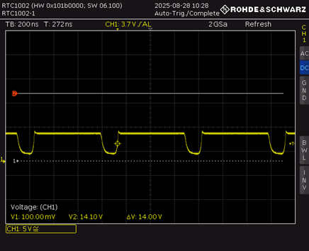
- With the output signal in this state, the component dissipates a lot of heat and does not exit this state; it only returns to normal operation if it is turned off and cooled.
- If the external +5V source has limited current (limited to 400mA), the converter enters a fault condition, causing the switching to behave as follows:


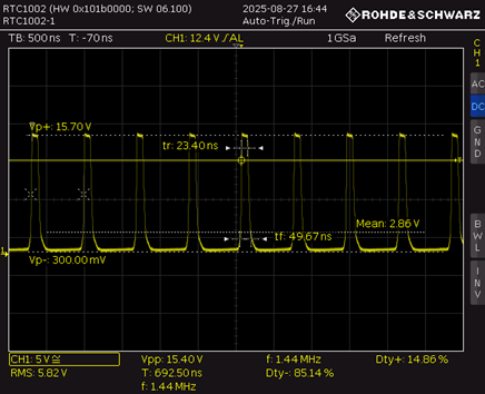
- After a few seconds, switching returns to normal operation.

