TMUX1219: TMUX1219 destroyed

Part Number: TMUX1219


Hi All
I'm using the TMUX1219 before an optocoupler, to handle polarity of the connected equipment.
My design is a MIDI input on TRS connector, polarity can be votage on the tip and signal on the ring, or the opposite.
My schematics are below :
TMUX switch selected by MCU GPIO.
TMUX powered from 5V


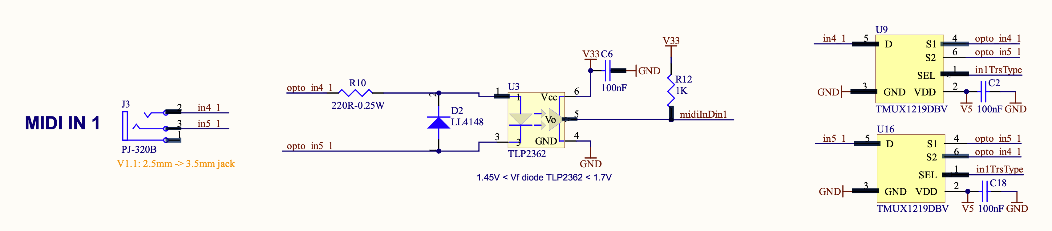
MIDI input is a current loop of about 10mA.
The jack connected to the TRS could be

Type A :

5V -- Res 220R -- Tip
0V (when signal) -- Res 220R --> Ring

or

3.3V -- Res 33R -- Tip
0V (when signal) -- Res 10R --> Ring

Type B :

5V -- Res 220R -- Ring
0V (when signal) -- Res 220R --> Tip

or

3.3V -- Res 33R -- Ring
0V (when signal) -- Res 10R --> Tip

image-20240711123850-1.png

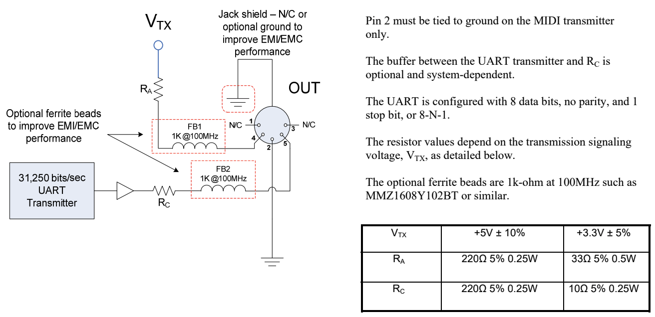
I'm observing the TMUX1219 destroyed depending on the connected equipment.
What could be the cause ?
I'm thinking about a floating ground issue, I mean there is no cmmon ground between the connected instrument and the TRS input, so the voltage applied to the TMUX1219 inputs could be out of specification ? For instance 6V ?

How to solve this issue ?
Do you thing using TVS diodes to clamp the TMUX inputs to VCC + 0.5V and GND - 0.5V could protect the IC ?

Thanks for any tip you can provide.
Regards


  • Responding to myself.
    The ground of the connected instrument is present on the jack sleeve.
    If I connect the ground of TMUX1219 to the jack sleeve, without connecting the ground to my board, that means the TMUX inputs will be constrained correctly since the MIDI output is always 5V or 3.3V (through the resistors mentioned above).
    But in that case, how to provide the 5V to supply the TMUX ?

  • Hi Jerome,

    I'm not sure I understand your concern for providing 5V to the MUX. If you give it 5V and make sure the grounds are connected throughout the board, that should be ok. 

    If you are still seeing catastrophic failure, I would recommend probing each of the MUX channels to see if you are actually getting the voltage (& current) you expect on each channel.

    Best,
    Katy

  • My idea is to keep the ground separated on the sender and receiver, that is the original purpose of the optocoupler.
    Connecting the TMUX ground to the sender ground (isolated from the receiver ground) would solve the signal constrained between Vcc and Gnd of the TMUX, but how to power the TMUX with 5V if the grounds are separated ?


  • Hi Jerome,

    Can you replicate the issue while monitoring the inputs/outputs of the mux as well as the supply current?

    What kind of failure are you seeing? Physical damage? Did the mux recover, etc? Please elaborate on the failure.

    Thanks,
    Katy