A related question is a question created from another question. When the related question is created, it will be automatically linked to the original question.
If you have a related question, please click the "Ask a related question" button in the top right corner. The newly created question will be automatically linked to this question.
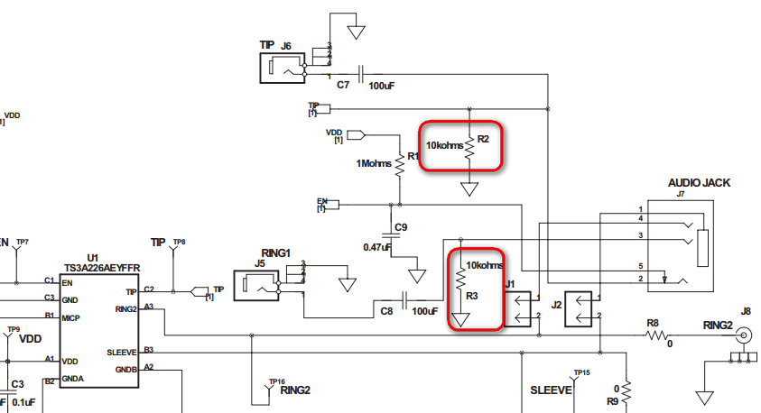
In the datasheet it describes that the EN pin C1 requires a rising edge to initiate the detection sequence and says it can be connected to the headphone jack to allow the insertion event to trigger the rising edge.
The audio jack J7 has a mechanical normally closed switch between pin 5 and pin 2. When an headphone is plugged into the jack the normally closed mechanical switch opens the electrical connection between pin 5 and pin 2 of J7. The 1Mohm R1 pull up resistor and 10kohm R2 pull down resistor creates the rising edge the EN pin needs for the TS3A226AE to initiate the detection sequence. R3 is simply used to balance the L and R channel since the tip pin had 10kohm resistor for the detection sequence.
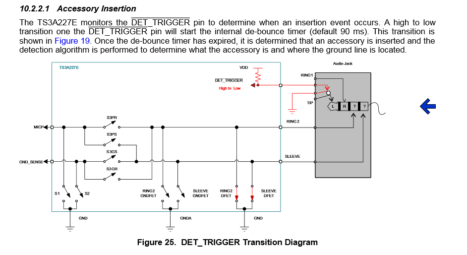
Our newer TS3A227E datasheet and EVM guide have a little bit more clear explanation on how the audio jack can be connected to the IC in order to have the insertion of a headphone into the audio jack create the rising or falling voltage.