Because of the Thanksgiving holiday in the U.S., TI E2E™ design support forum responses may be delayed from November 25 through December 2. Thank you for your patience.

This thread has been locked.

If you have a related question, please click the "Ask a related question" button in the top right corner. The newly created question will be automatically linked to this question.

TS3DV20812: TS3DV20812 cannot connect the two devices

Part Number: TS3DV20812
Other Parts Discussed in Thread: TS3L500

Hi Team,

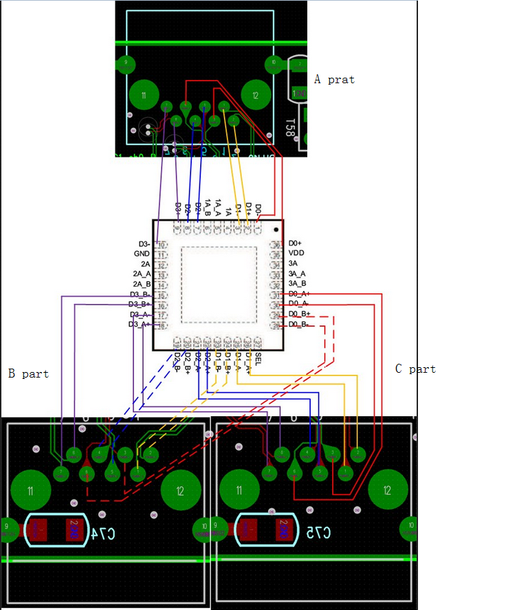
The customer is using TS3DV20812 for gagabit LAN signal switching.  The attach is his block diagram. 

If there is not the TS3DV20812 device, the A part can connect the B part. But when the Sel pin is the high level, the A part cannot connect the B part. 

For the Sel pin, the  high level voltage is 3.2V and the low  level voltage is 0V.  VCC is 3.3V for TS3DV20812.

What is the reason? How to solve the issue?

Best Wishes,
Mickey Zhang
Asia Customer Support Center
Texas Instruments

  • Mickey,

    Thank you for testing the A to B signal path without the TS3DV20812 device.  This helps us know that placing the switch in the signal chain is disrupting the signal. 

    Is there any issue with communication from prat A to part C through the TS3DV20812? 

    Is there any signal passing through the TS3DV20812?  Could you probe the select pin, an input (DX+/- pin), and its corresponding output pins DX+/-A and DX+/-B?  We would like to see a clean input signal being switches to a clean output signal by toggling the select pin. 

     Thank you,

    Adam

  • Hi Ada,

    Thank you for your reply.

    I will confirm if there is any issue with communication from prat A to part C through the TS3DV20812 with the customer。

    What do you mean by "probe the select pin, an input (DX+/- pin), and its corresponding output pins DX+/-A and DX+/-B? We would like to see a clean input signal being switches to a clean output signal by toggling the select pin"? Would you like to get the voltage waveform for an input (DX+/- pin), and its corresponding output pins DX+/-A and DX+/-B?
  • Mickey,

    Yes I would like to see a voltage wave form of the digital control signal, input, and output. I would like to see if there is any voltage distortion as the signal is passing through the TS3DV20812 device and if the control signal is operating correctly.

    Thank you,
    Adam
  • Hi Adam,

    A part can communicate with part C through the TS3DV20812. The customer uses RJ45 lines.

    The waveform is in the attach. 

    The customer provides  the Maximum Error table. Please check the word for the attach.

    The customer suspects that theer are some issues for the layout .And he also provides the layout. Please check the attach.

    The customer has another two questions:

    Q1: What are the differences between TS3L500 and TS3DV20812?

    Q2: The customer has set  the impedance to 100ohm for the differential signals.  Is the impedance set to  100ohm for the differential signals? Or any other resistance?

    4341.Maximum Error table.docxMaximum Error table.docxAUTOMATIC_RELAY_BOARD_V3.0(1).pdf

  • Mickey,

    That is good news that they can communicate to part C through the TS3DV20812.  We can rule out the TS3DV20812 performance limitation causing the issue.   I think we need to examine the difference between part C and part B.

    What is the signal you sent with the scope shot?  Is it the input or output?  How does it compare with the input or output?  How does the signal compare to part B and part C.  We would like to see a working signal compared with the non working signal.  

    The yellow signal you sent has a voltage that is out of specification for the TS3DV20812.  It is not recommended to place a negative signal through the signal path.

    Q1) The main difference between the TS3L500 and TS3DV20812 is the package size. 

    Q2) None of our passive switches have internal impedance matching circuitry. 

    Where in the layout is the TS3DV20812 device?  Is the customer ok with the layout being on a public forum? 

    Thank you,

    Adam