This thread has been locked.

If you have a related question, please click the "Ask a related question" button in the top right corner. The newly created question will be automatically linked to this question.

MUX36S08: How much leakage current about the MUX36S08?

Part Number: MUX36S08

Dears,

I have s product used CD4051 multiplexer, but I found the chip have a great leakage current when the input have power on. I don't konw whether the chip input construction or other reason.

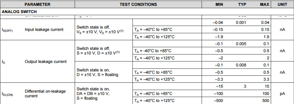
And then, I have choose a high input voltage multiplexer(MUX36S08) to replacement the CD4051. I want to konw what about the chip leakage current and the input port structure. Thanks!

Beat Regards!

Jacking

  • Hi Jacking,

    CD4051 tends to have higher input leakage current than MUX36S08 does for major two reasons. First, CD4051 has higher ESD ratings than MUX36S08. Generally, it is a trade-off between ESD ratings and input leakage current. Second, TI keeps improving the semiconductor material performance. MUX36S08 was released in 2016 while CD4051 was released in 1998.

    Here is the MUX36S08 leakage performance for your reference.

  • Dear Fan,

    Thanks for your reply!

    If the chip no supply power, the other pin have voltage(likeS->D), because I found the CD4051 have a little hot when the chip no work and the S to D withstand voltage, Could you tell me the reasons and how to process it ? and did the MUX36S08 will have the same problem ? Thanks!

    Best regards

    Jacking

  • Hi Jacking, 

    In your case, when VDD is not present and the analog input/output pins are pulled up to high voltage, there is a current path from the analog input/output to VDD pin. If you can let us know the voltage level at analog inputs/outputs, we can roughly estimate how much current is conducting. In general, this current is large and can generate sensible heat. This is a very common ESD structure, so most chips including CD4501 and MUX36S08 will have this phenomenon.

    It might be helpful if you could share with us your design and schematic. We can definitely help you investigate solutions, for example adjusting your power supply sequence or adding an isolation switch between our multiplexer and your other chips.   

  • Dear Fan,
    Could you tell me how to calculate the current and the internal circuit structure of ESD? Later on, I will upload the SCH of my design. Thanks!
    Best regards
    Jacking
  • Hi Jacking,

    Would you please let me know

    1. your tentative voltage supply, +/-15V, or +/-18V or 0~36V?

    2. the maximum analog input voltage swing?

    3. the maximum leakge current budget when supply is off?

    4. the source impedence of the sensor, the source of analog input?

    Based on these 4 questions, you and I can work out a circuit topology. Given a specific circuit topology, I can explain how to caculate the leakge current when power off.
  • Dear Fan,
    Thanks!
    I don't know what's mean the maximum leakge current budget and how to get the source the impedence.
    Beat regards
    Jacking Jin
  • Dear Fan,
    Thanks for your suggestion!
    We have a solution for the problem, the function is OK . Thanks again.
    Beat regards,
    Jacking Jin
  • Hi Jacking, 

    I am glad that you and your customer have figured out a solution to your system. It will be very appreciated if you can share a bit more about how your solution looks like.