This thread has been locked.

If you have a related question, please click the "Ask a related question" button in the top right corner. The newly created question will be automatically linked to this question.

SN74LV4051A-Q1: Consideration of lead current

Guru 16770 points
Part Number: SN74LV4051A-Q1

Hi

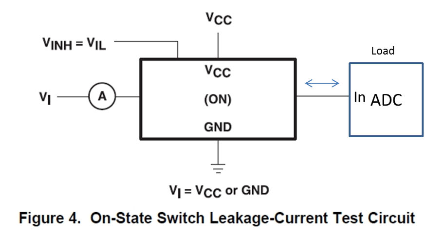
On state switch leakage current (IS(on)) can be tested in the circuit like figure 4.

If the one side is not open (connecting to any load), is IS(on) varied out of 2uA (datasheet spec)?

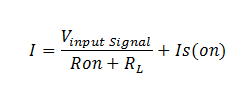
For example, should we consider the additional current to estimate total current like following?

Total current = leak current (Is_on) + additional current (leak current from load)

BestRegards

  • Hello na na78,

    From Kirchhoff's current law we know that essentially any current that flows into a node should also flow out of a node.  With our multiplexers or switches there are essentially two to three input paths and one output path.  The input paths include the input signal pin and the ESD protection diodes going from the ouput pin to either ground or Vcc (figure 1 and 2).  The output path is the load which feeds into the ADC.  When the the switch is disabled, the path between the input pin and output pin goes Hi-Z, which can be approximated with a giga-ohm resistor.  So from this path we expect very little current.  We also expect this resistance to be significantly higher than that of the ADC load, so the voltage should be nearly zero.  Since this voltage is nearly zero, we can expect that the ESD diode between the output pin and VCC will be reverse biased.  From the the typical IV curve for a diode (figure 3), it can be seen that there is some leakage (Is(on)) in the reverse bias state and this should be more significant than the current from the input pin.  In the configuration shown in figures 1 and 2, there will always be a diode reverse biased regardless of whether the switch is enabled or disabled.  When the switch is off, it should limit the current going to the ADC to IS(on).  However, when the switch path is enabled, the current will be as shown in Equation 1.

    Figures 1 and 2

    Figure 3

    Equation 1