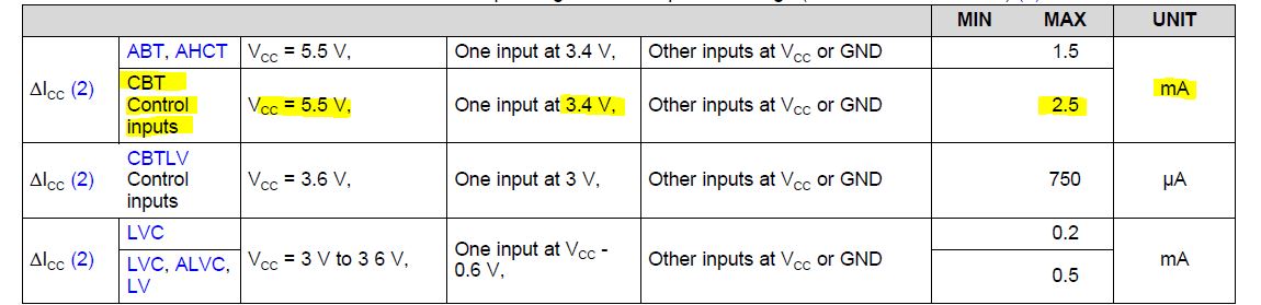
Vcc will be 5V however the Select and OE pins will be driven by MCU at 3.3V. On the SN74CBT3251, are the Select & OE pins isolated from Vcc? Or do we need to ensure that the MCU has 5V tolerant pins?
Thank you
Vcc will be 5V however the Select and OE pins will be driven by MCU at 3.3V. On the SN74CBT3251, are the Select & OE pins isolated from Vcc? Or do we need to ensure that the MCU has 5V tolerant pins?
Thank you