This thread has been locked.

If you have a related question, please click the "Ask a related question" button in the top right corner. The newly created question will be automatically linked to this question.

SN74CBTLV3257: Got output over spike issue

Part Number: SN74CBTLV3257
Other Parts Discussed in Thread: TMUX1574

Hi Team,

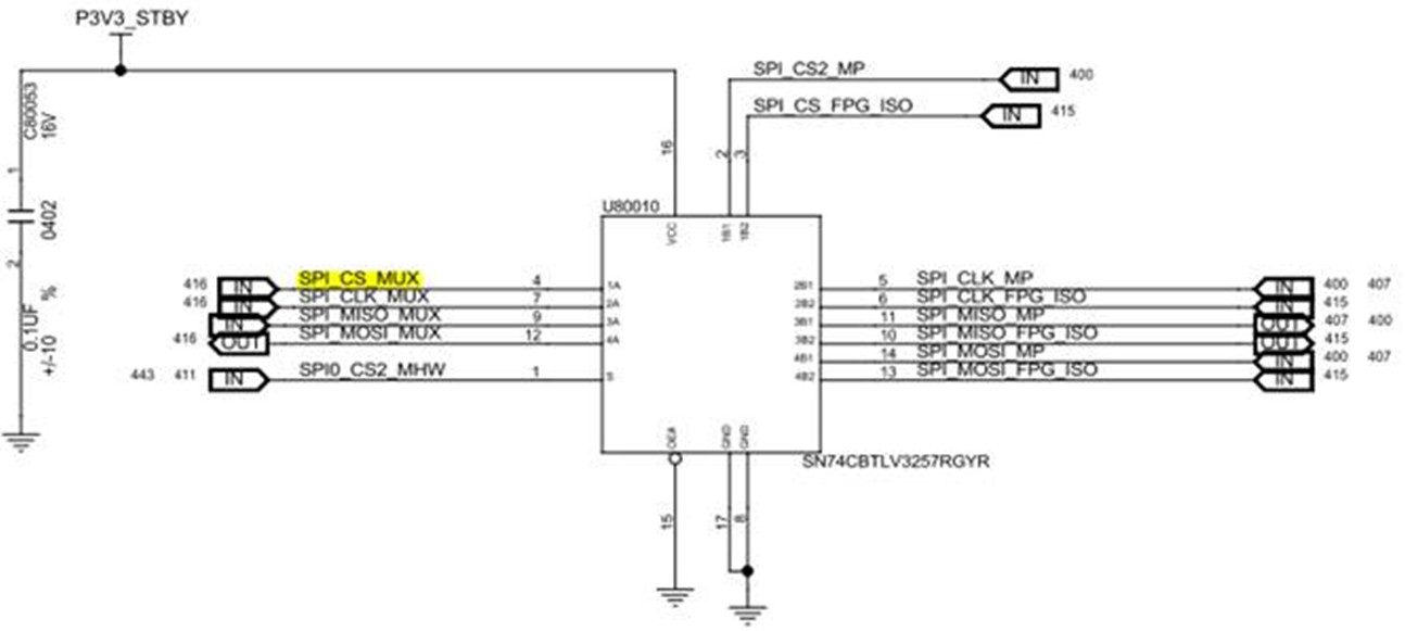
As we know, SN74CBTLV3257 is a passive switch, essentially the output will be the same as the input.

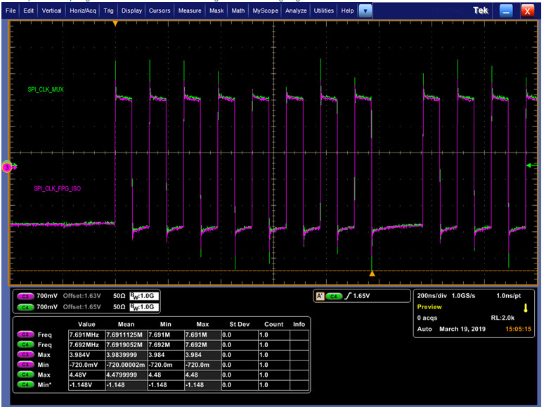
But we a over spike issue at output side. Please refer to below waveform and schematic. Any reason to cause that? And please give us some suggestion to resolve.

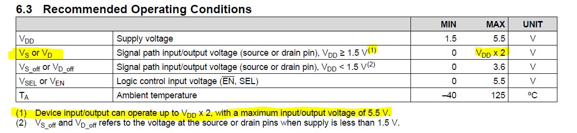
A side connects to EEPROM, and we already remove it as we measure the waveform. Vmax and Vmin spec is -0.6~4.0V.

Thanks

Channel 4: A side : SPI _CLK_MUX ; Channel 3: B side : SPI_CLK_FPG_ISO.   You can see A side signal is enlarged by 1.12 times.

  • Daniel,

    You said you removed the switch to check the waveform and measured the voltage to range from -0.6 to 4.0V.  Would you please show us the scope shot with the switch removed?

    The signal range without the switch -0.6V to 4.0 V is outside the recommended operating conditions of this device of 0 to Vcc.  The new TMUX1574 device with Vcc = 3.3 I/O signals can range from 0 to 5.5 V. 

    I'm confused about your scope shot.  It looks like SPI signals are -1.4 V to 1.4 V.  The SN74CBTLV3257 device cannot support this voltage range.  Are you grounding the scope probe properly? 

    If are able to adjust the driver to be within recommended operating conditions may still have overshoot and undershoot which usually caused by impedance mismatches in the signal chain.  You can try to using some series termination resistors on the receiver side to better match the impedance across the signal chain or reduce the frequency of the signal to slow down the signal rise and fall times.

    Thank you,

    Adam

  • Hi Adam,

    Thanks for your help.
    We did not remove SN74CBTLV3257. The correct is we remove the A side device (EEPROM) to avoid its effect.
    Vmax and Vmin spec is -0.6~4.0V means our SPI range spec.

    As your advice, we can try some series termination resistors on the receiver side in advance.
    Does it means series a resistor on SPI _CLK_MUX ?
    Does impedance mismatches means the impedance gap between SPI _CLK_MUX (A side)and SPI_CLK_FPG_ISO (B side)?
    What resistor value you suggest?

    Thanks
  • Daniel,

    What does the signal look like if you remove the mux and short the signal path? Does the overshoot still exist?

    Let me think about the system a different way. There could be inductance on your signal path could be creating the voltage spike due to a strong driver causing fast change in current. Placing series resistance could help with the overshoot by weakening the driver strength. You can experiment with starting with small resistor values like 50 ohms to weaken the driver a little bit and increase it until it is acceptable in your system if you are seeing positive effect.

    The edges in your signal look pretty clean as well so you may also be able to add some capacitance on your line to slow down the voltage spikes.

    Let us know what you think,

    Thank you,
    Adam
  • Dear Adam,

    Many thanks for the advice.
    We would try to remove the mux and short the signal path to see if the overshoot still exist.
    And do the resistor and capacitor experiment.

    Thanks