This thread has been locked.

If you have a related question, please click the "Ask a related question" button in the top right corner. The newly created question will be automatically linked to this question.

TS5A3153: measuring 2mA of current consumption on the supply rail and this occurs only when one of the two digital inputs is driven at 3.3V and Vcc = 5 V

Part Number: TS5A3153
Other Parts Discussed in Thread: TMUX1119

e2e, 

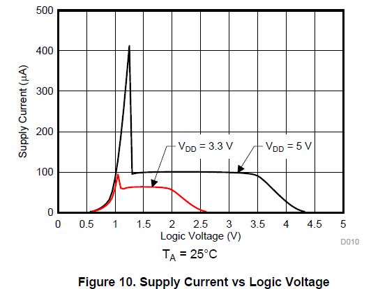
I'm currently testing TS5A3153 but coming across some issues.


Power Supply is 5V whilst EN and IN pins are driven by a 3.3V MCU.


According to the test results, they’re measuring 2mA of current consumption on the supply rail and this occurs only when one of the two digital inputs is driven at 3.3V. If this is forced to 0V or 5V, the current consumption is within the specified range.


Looking at the datasheet, there’s no evidence of such a behaviour.

Thank you,

Adam

  • Hi Adam,

    When the EN and IN pins voltage is not at Vcc or ground, there will be excess current consumption for this device.  This is due to the shoot through current when the switch is in an undefined state (voltage is between Vih and Vil).

    As long as you are operating within these specs then the current should be within the datasheet limit.

    See the below E2E posts explaining the same issue.

    Regards,

    Saminah

  • Hi Saminah,

    according to the datasheet the undefined state (i.e. voltage between VIL_max and VIH_min) causing the excess current consumption due to shoot through current should be 0.8V....2.4V, right?

    In my case, VIN and EN pins are at 3.3V that's not in the undefined state:

    1. Would you anyway expect this excess current consumption? If so, why?

    2. Since this condition is not mentioned anywhere into the datasheet, can it damage the device if it occurs as an extended condition over time?

    Please let me know

    Thanks

    Fabio

  • Hi Fabio,

    Yes, there will be current consumption when VIN and EN pins are at 3.3V. This will not damage the device but TI recommends the control logic inputs be at Vcc or ground to prevent the excess current consumption. 

    This application note explains in detail what is causing the increase in current consumption.  

    The new TMUX1119 device has better current consumption performance defined when the logic voltage is not at supply. 

    Thanks

    Saminah