This thread has been locked.

If you have a related question, please click the "Ask a related question" button in the top right corner. The newly created question will be automatically linked to this question.

SN74LV4066A: Does SN74LV4066A is able to prevent back-powering?

Part Number: SN74LV4066A
Other Parts Discussed in Thread: TMUX1511, SN74CB3Q3245, TMUX1109, TMUX1112

Hello,

In my design I use 4 UARTs (operating with 1V8 logic) for communications with different peripherals (like GPS, Bluetooth). If some peripheral is no needed then it is powered down and MCU RX/TX lines are set to high impedance. However, for debugging and testing purpose I have UARTs sniffer (with possibility to listen for data and to inject data) connected to these 4 UARTs (build based on FT4232). I've noticed that there is back-powering from FT4232 to disabled external peripherals. I wonder how to prevent this back-powering and one of my idea is to use switch like SN74LV4066A. However, because I don't know its internal structure I cannot be sure it will be working or not. Do you have any experience with SN74LV4066A and can advice if it is right solution? If SN74LV4066A is not the right choice then what is your recommendation?

Best regards,
Tadeusz

  • Hi Tadeusz,

    Thank you for using e2e.

    The  SN74LV4066A does not have a clamp to VCC on input or output. So this device cannot be back powered.

    One way to check if the device has high impedance when device is not powered is looking at the Ioff feature.

    We  also have the new TMUX1511 in similar configuration (1:1, 4 channel) to the SN74LV4066A, that offers powered-off protection (device maintains its high impedance (Hi-Z) performance even without power to the IC) along with additional features like 1.8-V compatible control inputs, Fail-safe logic/

    For more details on Here is the FAQ that explains "Powered off Protection" in more detail.

    Regards,

    Saminah

  • Hello Saminah,

    Thank you for your answer. I'm not sure if I understand you correctly. I'm asking for some switch that could be added on Rx and Tx lines between FT4232 and GPS/Bluetooth to prevent back powering of GPS/Bluetooth when they are off but I think your answer is about back powering of SN74LV4066A when it is not powered.

    Regards
    Tadeusz

  • Hi Tadeusz,

    Can you provide a block diagram of your application or a schematic and the voltage and datarates you would like to support?

    Regards

    Saminah

  • Hi Saminah,

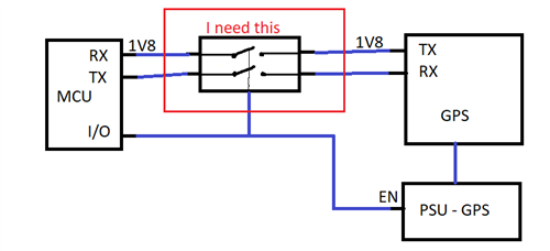
    To simplify, I need some sort of switch (for example 2xSPST) between MCU and GPS to disconnect TX and RX when GPS is not powered. Right now there is back powering - GPS sink current from RX/TX of MCU. UART baudrate is up to 1Mbps. I need switch marked below in red - when PSU for GPS is switched off then switch has to disconnect RX and TX. Unfortunately  it is not possible to power switch (marked red) from the same source as GPS.

  • Hi Tadeusz,

    As both devices mentioned earlier (SN74LV4066A and TMUX1511) are Off (high impedance) when EN is low, both devices can be used in you application and will protect your device from back powering over TX/RX.

    Additionally they have powered-off protection if the MUX supply is not present. This protects the the GPS when VCC is not present at the MUX but the MCU already sends RX/TX signals.

    Best regards,

    Ambroise

  • Hi Ambroise,

    Many thanks for answer. My example was simplified, for better understanding of my problem, to only one device but it is more complex and contains 4 peripheral devices connected to main board via UART and each or them can be powered on and off independently. In this case it is not possible just to set EN pin of SN74LV4066A to low because some other devices still can be active. Of course I can use multiple of SN74LV4066A (one per UART), however then I need a lot of space on PCB plus many additional components - all this introduce more complex PCB to design. I'd prefer some switch with control pin per each channel to connect/disconnect RX/TX and prevent back powering from this switch as well. Any suggestion?

    Regards,
    Tadeusz

  • Hi 

    In the SN74LV4066A , each switch section has its own enable-input control (C). A high-level voltage applied to C turns on the associated switch section only.

    You can connect each peripheral to each switch separately and control them through control C.

    Regards

    Saminah

  • Hi Saminah,

    In previous answer you wrote that SN74LV4066 is Off (and has high impedance) when EN is low - and I thought this is what I have to do. Now the statement is that it is enough to use enable-input control to "cut" line and prevent back-powering. So final question is "is it enough to use control pin for each switch to avoid back powering on controlled line and EN pin can be high all the time?"

    Regards

  • Hi Tadeusz,

    Both devices, SN74LV4066A and TMUX1511 control the switches with control (1C) or selecet (SEL1) pin. And to clarify they don't have a universal enable pin as seen on other devices.
    In both cases, when this contrl/switch pin is low the path from in to out is high-Z. This should be enough to prevent the GPS device to be powered on.

    In case the MUX is not powered on by VCC for any reason, the path from in to out will stil be high-Z as they have powerd-off protection.

    If I understand correctly you'll have to control 8 lanes on the peripheral side? 
    If you need to protect all four devices the easiest would be to use a 8 channel switch and connect 4 lanes for RX and TX respectively on the MPU side. Have a look at SN74CB3Q3245.

    If one of your devices does not need to be protected you can use a 2channel 4:1 switch and connect that device to the initial channel. Have a look at TMUX1109.

    Does this resolve your issue?

    Best regards,

    Ambroise

  • Hi Ambroise,

    Thank you for final confirmation that it is enough to use particular control-pin for each switch and no back-powering should happen. This is very good information.

    Unfortunately SN74CB3Q3245 cannot be used in my setup because it does not contain separate control pin for each switch. SN74CB3Q3245 has a single output-enable (OE) input pin - one for all switches.To be honest I cannot find in your products any device with more than 4 switches where each switch is controlled independently. Maybe I miss something on your switches page - if so could you please advice which chip has 8/10 switches with independent control pin for each switch? Otherwise I will have to use at least two SN74LV4066A.

    Regards,

    Tadeusz

  • Hi Tadeusz

    Using the SN74LV4066A with independent control for each channel will be your best option.

    Regards

    Saminah

  • Hi Saminah,

    Does TMUX1112 also give me back-powering protection when particular line is OFF? I'm thinking about TMUX1112 because it has less OFF leakage current than TMUX1115 (0.3nA vs 100nA). Does TMUX1112 also has high impedance on the switch when the corresponding select pin is pulled low?

    Regards,

    Tadeusz

  • Hi Tadeusz,

    When the particular switch line is OFF (via SEL pin) in TMUX1112, the high-impedance state for that switch is ensured and you are protected from "back-powering" other devices in your system. TMUX1112 is a good choice, due to less OFF leakage current, to protect your downstream components.

    Hope this helps!

    Regards,

    Kate