This thread has been locked.

If you have a related question, please click the "Ask a related question" button in the top right corner. The newly created question will be automatically linked to this question.

TMUX6119: Is LM555 output good for select pin.

Part Number: TMUX6119
Other Parts Discussed in Thread: LM555

Ronald Michallick very kindly provided analysis and the following information appended below regarding a part of my circuit involving a LM555 timer to provide a high and low frequency pulse to a TMUX6119 switch.

But he has now confounded me by saying:

"The new board layout looks proper. Start a new thread with TMUX6119 as the part number and ask them if LM555 output is good for select pin. 

Someone else will answer. Almost all questions with LM555 (as the part number) will be answered just by me."

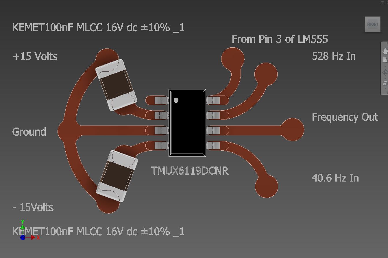
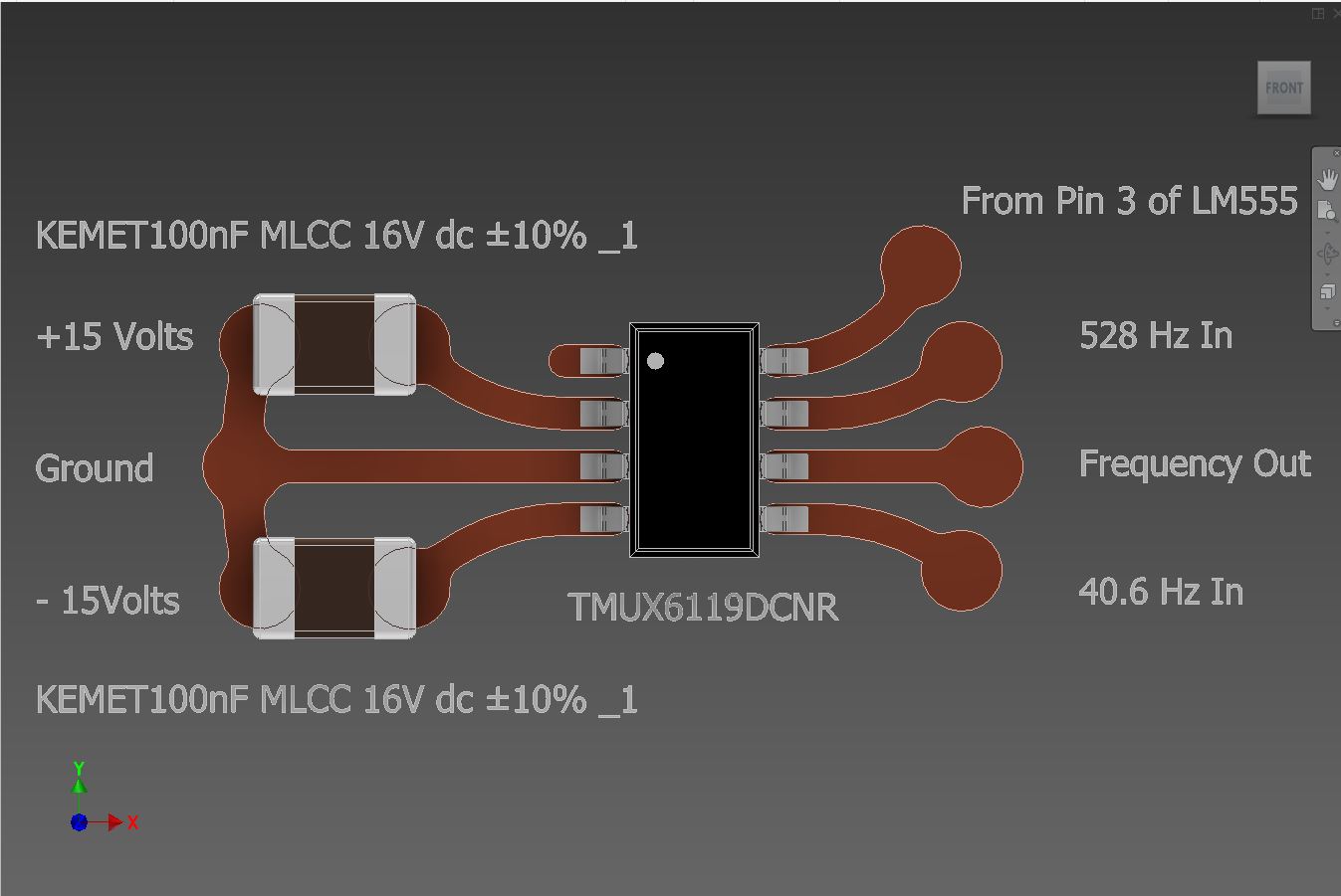
Is it thus possible for the circuit that I have appended below to be checked for correctness please?

Finally the curved layout style is unique to us as an organisation. In time as our work is made public, you will understand the need for our method. In short, we are not just interested in the flow of electricity, but in the flow of Bioenergy and thus our circuits are designed more akin to how nature would have them.

I would be most grateful to anyone whom can accurately assess my layout please as advised by Ronald.

Thank you so much.

Christopher J James


Christopher,

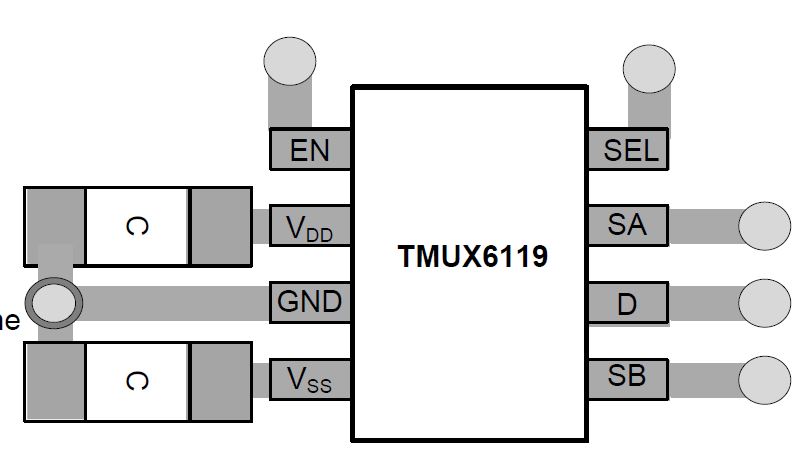
No interconnects needed. Just connect pin 3 to the select pin on the analogue switch IC. Ground goes to ground. VCC+ can use same positive supply that the analogue switch uses. 

The data sheet suggests adding bypass capacitance to power pin (+15V)

0.1 uF bypass ceramic capacitor
1 uF electrolytic bypass capacitor

Using equations in the data sheet , here are the results.

The TMUX needs a VIL less than 0.8V , the LM555 can meet that need.

The TMUX needs a VIH greater than 2V, the LM555 can meet that need.

I have said this multiples times, but I will say it again. LM555 pin 3 can connect to the TMUX directly without any other components. 

LM555 low output will be near 0V. This level is valid (less than 0.8V). LM555 high output will be roughly 14V. This level is valid (greater than 2V, but less than or equal to VCC, 15V).

The data sheet suggest adding bypass capacitance to power pin (+15V)

0.1 uF bypass ceramic capacitor
1 uF electrolytic bypass capacitor

Using equations in the data sheet , here are the results.

The TMUX needs a VIL less than 0.8V , the LM555 can meet that need.

The TMUX needs a VIH greater than 2V, the LM555 can meet that need.

Regards,
Ronald Michallick
Linear Applications

  • Hi Christopher,

    Based on the details you provided (and Roland's analysis), you can connect the output of LM555 pin 3 to the TMUX6119 SEL pin directly without any other components as it meets the VIH and VIL levels provided in the datasheet.

    Make sure you properly supply decoupling capacitor ranging between 0.1 μF to 10 μF at both the VDD and VSS pins to ground.

    Regards

    Saminah

  • Dear Saminah,

    Thank you so much.

    This is my circuit for the  TMUX6119, is it OK and does it provide enough of a heat-sink?

    Also are you able to check that the Capacitors are of high enough value, please?

    These are the guidelines:

    11.1 Layout Guidelines
    Figure 37 shows an example of a PCB layout with the TMUX6119.
    Some key considerations are:
    1. Decouple the VDD and VSS pins with a 0.1-μF capacitor, placed as close to the pin as possible. Make sure
    that the capacitor voltage rating is sufficient for the VDD and VSS supplies.
    2. Keep the input lines as short as possible. In case of the differential signal, make sure the A inputs and B
    inputs are as symmetric as possible.
    3. Use a solid ground plane to help distribute heat and reduce electromagnetic interference (EMI) noise pickup.
    4. Do not run sensitive analog traces in parallel with digital traces. Avoid crossing digital and analog traces if
    possible, and only make perpendicular crossings when necessary.

    Thank you once again.

    Christopher


  • Hi Christopher,

    Thank you for sharing the TMUX6119 layout.

    The decoupling capacitors look good - they follow the recommendation from the TMUX6119 datasheet.

    I also checked the logic levels. The LM555 can meet that need for TMUX6119 VIH/VIL levels.

    Thanks

    Saminah.

  • Dear Saminah,

    Thank you so much for checking the layout and values.

    I did realise afterward that I had omitted to ground both the +15v and -15v supplies. Hence, I have adjusted the layout and added the grounding as per the following sketch, which other than that has not chenaged.

    Thank you so much, once again.

    Christopher

  • Dear Saminah,

    Thank you so much for checking the layout and values.

    I did realise afterward that I had omitted to ground both the +15v and -15v supplies. Hence, I have adjusted the layout and added the grounding as per the following sketch, which other than that has not changed.

    Thank you so much, once again.

    Christopher

    PS I have attached the manufacturers suggested linkage of the supplies to the ground .