This thread has been locked.

If you have a related question, please click the "Ask a related question" button in the top right corner. The newly created question will be automatically linked to this question.

SN74CB3T3306: Seeing Unexpected Voltage Levels

Part Number: SN74CB3T3306

Hello,

I am using the SN74CB3T3306DCUR to connect a 3.3V I/O to an signal that could be up to 5V. I need to be able to either receive a 3.3V or 5V signal OR transmit a 3.3V signal. I have this part's VCC connected to 3.3V and the OE# pins tied to ground. The B terminals are connected to my device and the A terminals go to connectors so that a signal may be cabled in or out.

The problem that I am seeing is the output voltage at the B terminal is low when there is a 3.3V signal on the A terminal input from the connector.

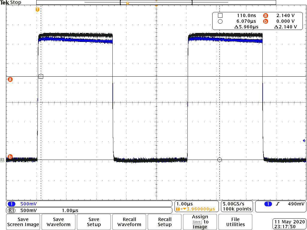
The image below shows my input signal. The dark gray waveform is the 3.3V signal incident upon the A terminal measured at the A terminal. The blue waveform is the signal output at the B terminal and measured at the B terminal using the same probe.

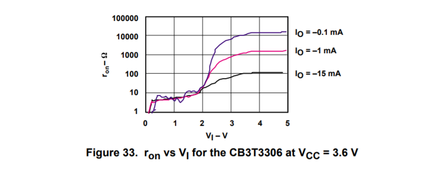
The signal initially rises to the correct level but then gradually falls to about 2.1V. There is a 10k pull-down at the input of my device on the B terminal side of the bus switch. While this functions, I would like to understand why the signal drops to this level. From the datasheet, I would expect this signal to be close to VCC with current less than 1mA. Have I misunderstood the datasheet about this part?

Do I require a pull-up on the B terminal?

Now, when I drive the B terminal with my device, I get a reasonably good signal on the A terminal. If you look at the scope capture below, the dark gray trace is the 3.3V signal driven on the B terminal by my device and measured at the B terminal. The blue trace is the signal at the output A terminal measured at the A terminal. The signal is loaded with an oscilloscope set to 1 MOhm input.

This signal gradually drops to about 2.95V, which is more acceptable. Why does it behave differently in this direction?

Thanks for your help.

  • Hi Jason,

    The CB3T line of switches uses a series N-Mosfet as the switch. The CB3T family has a gate voltage of  ~VCC + VT when the input voltage Vi > VCC + VT and the output will be VCC. However when Vi = VCC, Vo =/= VCC. To be able to pass VCC to the output a transmission gate architecture can be utilized to a better effect, but they have other considerations as well. 

    For more information on how switch architecture can impact performance our precision lab video of switch architecture is a quick tutorial:

    What are common switch architectures?

    With the discrepancy that you described above , the voltage drop from A to B is substantially larger than the voltage drop from B to A. You are loading terminal A with 1MOhm load when measuring A, and when Measuring B, there is a 10K ohm Load. The difference in loading can affect the Ron of the switch, as well as the voltage divider between switch resistance and load resistance.


    The picture below describes Ron versus input voltage for different load voltages: 

    To make sure that this is the problem, I would short the signal path with a small resistor to see if it is a loading issue and not an issue with the switch. This will also allow you to test it without changing the loading conditions on each output. 

    This figure comes from our App note on the CBT/CB3T/CB3Q Families, which I have included in here for reference:

    CBT-C, CB3T, and CB3Q Signal-Switch Families
     

    Best Regards,

    Parker Dodson

  • OK, it sounds like I probably need a pull-up according to this. I tried asserting the internal pull-up but it is too weak to fight the 10k pull down.  I am afraid that if I used the NMOS/PMOS parallel switch that it would pass 5V to my receiver. I will solder on a pull-up to 3.3V at the receiver when I can make it back to work and see what happens. Thanks.

  • Hello,

    I managed to get my boards reworked this morning to remove the pull-down and assert a pull-up in my receiver. I now have acceptable signals. Thanks for the help, my issue is resolved.

    -Jason