This thread has been locked.

If you have a related question, please click the "Ask a related question" button in the top right corner. The newly created question will be automatically linked to this question.

TS3DS10224: NTSC PAL DIFFERENTIAL VIDEO SWITCH CAT6 CABLE

Part Number: TS3DS10224

Can the TS3DS10224 analog mux be used to switch differential NTSC/PAL video?

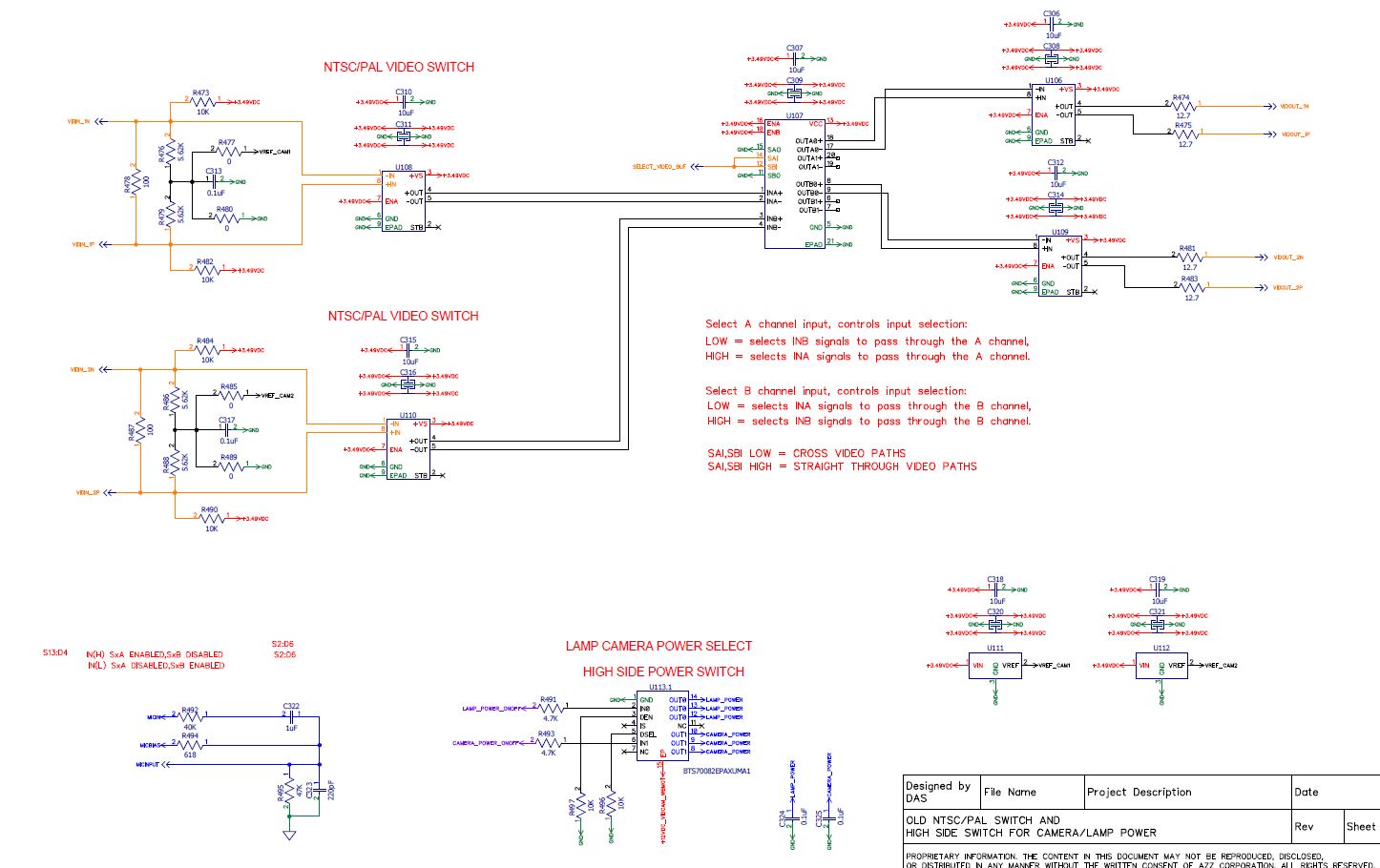
I have a need to switch differential video and not single ended.

I have two camera systems that use a balun, converting the SE video to Differential, with singals transported over  Cat6 cables of which need to be cross-pointed 2X2 to two respective monitors.

I can use  a simple analog switches in the path however I am looking for a more elegant solution.

Thank you.

  • This is strictly used as an analog switch with analog signals.  The differential analog signal is transmitted over Cat6e cable.

  • Hi David,

    What is the bandwidth / max datarate requirement for your application?

    The NTSC/PAL video bandwidth is ~upto 7-8MHz. The TS3DS10224 has supports high bandwidth of 1.2GHz (typ). You can use any of our analog switches for National Television System Committee  signals, so long as the switch matches their bandwidths and voltage levels.

    Regards

    Saminah

  • Hello Saminah,

    I have two  balun tranformer coupled NTSC signals as my inputs to a 2x2 cross point switch routed to two monitors. Since this over CAT6 I have to use two baluns for each channel to drive the video over the twisted pair.

    I assume I will have to level shift the signals so that common mode voltage is not violated. What is the common mode voltage of the MUX I did not see it in the data sheet.

    If I use the Analog I/O voltage then it would translate that Vcm is 0-VCC.

    I like to use the TS3DS10224 alone or in conjunction with the Analog Devices video filters obviously with  the MUX acting as the cross point switch.

    Any suggestions on  how to address the floating NTSC signal and the output driving the Monitor balun is greatly appreciated?

     I can couple ac or dc just that I cannot violate voltage requirements. I can also level shift ~+500mv so that the input voltage never below GND.

    Analog video and use of transformer coupled signals back to back is not my specialty and all help is greatly appreciated.

    The only other way I know is to use op amp with bi-polar supplies then level shift then cross point switch. I am looking for a simple elegant solution.

  • Hi David,

    Couple of questions and comments:

    All our signal switches are simple FET switches without any drive capability - you would need a driver to the video over the twisted pair.

    Why do you have a floating NTSC signal - See more details here how to handle floating signals in a switch.

    You should have each line referenced with respect to ground. As long as the IC is grounded to the same ground as the T-Line Termination  the IC can handle that without any issue.

    We also have some video switches that you can look at and also our 2:1 switches (device search tool) can be used back-to-back (because switches are bidirectional) to achieve crosspoint/exchange functionality. This may be an option that improves performance, size, or price, depending on system requirements.

    Regards

    Saminah

  • Hi Saminah,

    The two cameras are part of an existing legacy system that route to two dedicated monitors, denoted LCD. Hence CAM1-LCD1 AND CAM2-LCD2 pairs.

    On the legacy system, each camera link uses two baluns as the coaxial SE is transmitted over Cat6, DIFF, then converted back to coaxial SE.

    The new camera system needs to be crosspoint so that the monitor can be switched to the other camera. Hence CAM1-LCD2 AND CAM2-LCD1 pairs.

    Our cameras cannot be retrofitted and have embedded baluns within. The output of the cameras are isolated differential. There are non isolated type baluns however we use the isolated type as in the diagram shown in prior reply.

    With this in mind, I have two transformed isolated differential signals that need to be cross-point switched to meet the specifications for the new system.

    I agree that the NTSC input signal, 1Vp-p,  to the cross-point switch is floating and it needs to referenced to GND of the system. A simple resistor to GND on each input NTSC1+,NTSC1- may not be sufficient because the signal range is +0.5V to -0.5V, bipolar signal due to the balun transformer. Unless I am incorrect this negative swing cannot be handled by the switch because  the common mode voltage is 0-4 for either input. This is where you perhaps can provide clarity as I am uncertain on this issue.

    I know that I can level shift the inputs by +0.5V using either a split termination on the input with the center tap driven by a buffered +0.5V reference, or using simple resistors divider from VCC-RES-SIG-RES-GND as long as the RES network does not change the RTerm of 100 ohms drastically.

    I am going to review your video switches as well floating signals in the links.

    I am currently using a fully differential Video Filter from Analog Devices, ADA4433-1 to drive the remaining half of the CAT6 which has the monitor aka LCD balun attached.

    I agree using two video 2:1 switches is perhaps the simplest and most elegant solution. I have already looked at that once before and will review again.

    Just as a side note, I have used a FET switch as a cross-point switch in the first design. On the bench everything works well however there is extreme noise injected into the video stream when our equipment is in operation. I am uncertain where the source of the noise however it is unacceptable and am I researching to find a solution. Because time is critical I have to do my best to try to solve this problem.

    I am the senior hardware engineer for our automated robotic welding systems both MIG and TIG. This is one of the noisiest environments that exists and it is incredibly difficult to design for. Our systems become complex and while trying to maintain signal integrity of the sensitive electronics that drive the system I am often challenged everyday.

    I greatly appreciate your response.

    Sincerely,
    David

  • Hi Saminah,

    Cost is not an issue that is of any concern. I am generally space constrained on the pcb. Once again cost is of no concern.

    I need a solution that is robust enough to withstand the environment as it exists in this field.

    Video is not my specialty however I always accept a challenge.

    Thank you,

    David

  • Hi David,

    Thanks for sharing the details.

    Our mux will not help to make the system robust in noisy environments. You need to ensure that the system has enough margin for noise. 

     When it comes to selecting a mux, two key specs that you need to care about are the signal range and the bandwidth. Please make sure that both the common mode range and the signal swing is taken care of when determining the signal range. 

    Regards

    Saminah


  • Hi Saminah,

    I do not see the common mode voltage specifications of the TS3D10224.

    My common mode voltage is 1.75V and signal swing is +/- 0.5V, 1Vp-p.

    I believe the signals will pass through without any issues.

    I have a very short input path from a video filter approximately 350mils and a very short output path that terminates into a high impedance (800K) input video filter input approximately  400 mils.

    Since these paths are well below any critical length it is unnecessary to have 50 ohm termination. If you feel otherwise please advise me.

    Also I do believe the pins are generic labeled so that I can switch INA+ with INA- to reduce any routing vias. Do you agree with this?

    I am passing buffered NTSC signals through the switch so the signals are not floating.

    If you see any issues in the diagram I have posted please relate them to me.

    Your advice is greatly appreciated.

    David

  • Hi David,

    Yes, the common mode voltage is not spec'd in the datasheet but you should be ok with the signals you mentioned - keeping them between 0-Vcc.

    I don't see need for 50Ohm termination - you can find more details in the the layout guidelines in the datasheet (section 11) 

    The pins are generic labeled so you can switch INA+ with INA- (they both represent A channel signal path) as shown in pin functions table. It depends of what signal you place on them.

    The schematic looks ok.  The Vcc has proper decoupling, SAI, SBI, SAO, and SBO are properly pulled up to VCC or down to GND to avoid undesired switch positions that could result from a floating pin, signal pins look good.

    Regards

    Saminah

  • Hi Saminah,

    Are you referring to 50 ohms termination on the unused pins OUTA1x and OUTB1x pins?

    I have added them as they are not in the original schematic.

    Since these pins are never used to the need to be terminated? or will unterminated OUT pins create noise within the IC?

    I believe that the output from the ADA4433-1 video filter to the input of the TS3DS10224 inputs do not need any termination since I am well below the critical length. The signals I am referring to are INAx and INBx additionally the OUTA0x and OUTB0x pins to the input of the  ADA4433-1 CAT6 drivers do not need termination.

    These pins have a very short path with INAx,Bx approximately 500mils and OUTA0x,B0x approximately 225 mils.

    If you think termination is needed on used signal paths please let me know.

    I greatly appreciate your advice. I am in the final routing phase today and releasing the project tomorrow.

    I look forward to your response.

    David

  • Hi Saminah,

    Sorry I misread that you do not see the need for 50 ohm termination.

    Do you need to add termination on the unused OUTA1x,B1x pins/

    The datasheet says that you should terminate them however I am working in an extreme limited space area of the pcb.

    Please let me know if I can omit these termination resistors on ununsed output pins.

    Thanks,
    David

  • Hi David,

    Unused pins for the signal paths INA, INB, OUTAx, and OUTBx must be terminated with a 50-Ω resistor to ground to reduce signal reflections in high-speed applications. 

    You can run into signal integrity issues if you do not use proper termination on unused signal paths.

    Thanks

    Saminah


  • Hi Saminah,

    High speed is relative to the design parameters of any system. I have approximately -55dB on my video signals and the rise time is considerably slow at 200-300ns.

    There are certainly no reflections at this rise time.

    Given this as the specification for NTSC video it would suffice to render usage of 50ohm termination ineffective.

    Although adding them does not degrade  signal integrity.

    Would you agree that this is more or less the correct way of analyzing the usage of these 50 ohm termination resistor?

    I would think they are not needed in this particular application. I know what the datasheet says and it is relative to "high-speed applications".

    Your feedback is always welcomed.

    Thanks,

    David

  • Hi David,

    Yes, your understanding is correct.

    For your application, if you don't see any impact on signal, you should be ok without the 50 ohm termination on signal lines. 

    This video (just like the datasheet) highlights when having the termination is important.

    Thanks

    Saminah