This thread has been locked.

If you have a related question, please click the "Ask a related question" button in the top right corner. The newly created question will be automatically linked to this question.

SN74TVC3306: GATE OF SN74TVC3306 is 2.9v, what's the reason and risk?

Part Number: SN74TVC3306
Other Parts Discussed in Thread: SN74LVC2G66

Hi team,

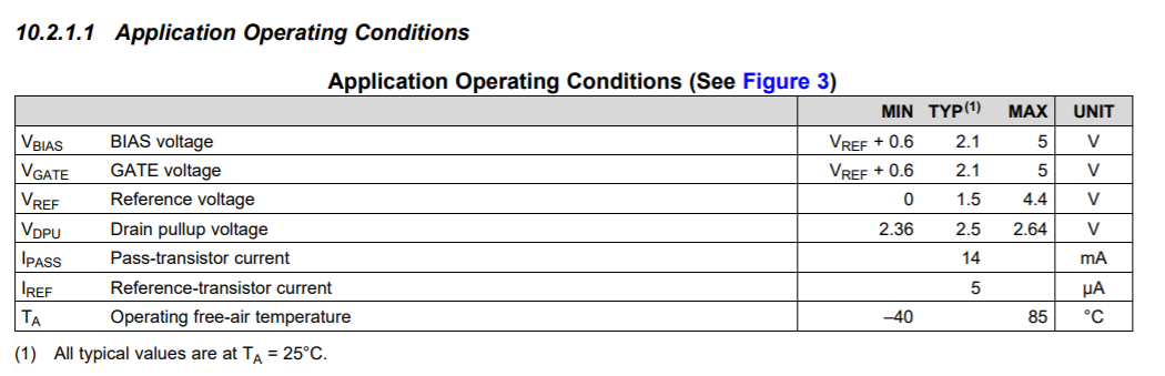
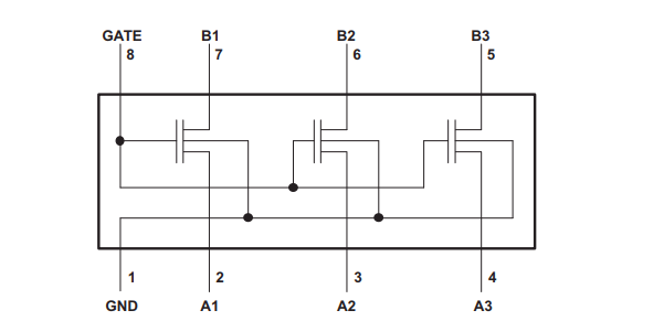
My customer is using the SN74TVC3306 now. The schematic is below. We want to check why the GATE SIDE voltage is only 2.9v, What's the reason? Whether it has risks? Thanks.

  • When this device works correctly, the gate voltage is less then 1 V above the lower supply voltage. (A current flows from the higher supply into B1, out of A1, and into the lower supply. The 200 kΩ resistor is required to limit this current.)

    But this device requires the higher supply to be at least 0.6 V higher than the lower supply, and that A1 is connected directly to the lower supply.

    If the purpose of this circuit is just to disconnect the I²C bus, then use a two-channel switch like the SN74LVC2G66.

  • Frank,
     
    The voltage drop is due to the resistor. This limits the current but you're still able to use this and stay within the recommended operational range of the device so no worries on the 2.9V. 
    A note on your design, however. Your reference (A1) should be 0.6V lower than your gate/Vbias (Gate/B1) though. As Clemens stated, to use this device as recommended, it requires that the higher Vbias be atleast 0.6V above the lower Vref. When you connect the Vbias to a Vcc voltage, you should then set your Vref to a supply between 0V and Vcc-0.6V This will cause the maximum clamp voltage will be set to Vref. 


    Thanks,
    Rami

  • Hi team,

    As you mentioned before,  this device requires the higher supply to be at least 0.6 V higher than the lower supply


    What's the influence or risks if they keep current schematic? i am not quite sure about this. Thanks.

  • Frank,

    Well the 0.6V is the threshold voltage required to conduct across the FET that is across B1 to A1. If you don't exceed this threshold there won't be a voltage forced through. This is used to determine the gate threshold of the two clamping FETs. So without this, the device wouldn't function properly and no clamping voltage could be set. 
    There's a good set of videos here on the LSF family which work similarly. Note that the threshold for these devices is 0.8V rather than 0.6V but the concepts are the same:

    https://training.ti.com/tlm-lsf-bias?context=1134826-1139264-1134790

    Thanks,
    Rami