This thread has been locked.

If you have a related question, please click the "Ask a related question" button in the top right corner. The newly created question will be automatically linked to this question.

TMUX1108: Proper layout and placement in partitioned ground board

Part Number: TMUX1108

Hi,

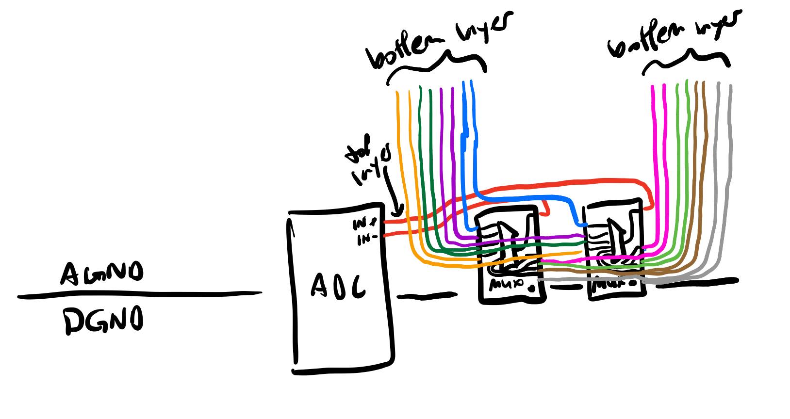
I am looking to use the TMUX1108 in a design with an ADC. I am currently planning on having a partitioned ground (AGND and DGND split, and connected at the ADC, analog power supply, etc), and am not clear on the proper layout of the TMUX1108 with regards to this. I would assume that the mux should also be placed across this partition, in line with the ADC and other ICs that have both digital and analog return currents (I have sketched what this would look like). However, as shown in my sketch, it would require these analog signals to border along the AGND and DGND partition. The slots in the PCB would also mean that a significant portion of the return current would not stay in the analog partition, and rather go through the digital partition, where it is susceptible to picking up noise and EMI. The alternative that I see is moving the mux to be completely within the analog partition, but this would result in digital signals in the analog partition. This may not be so bad as the address lines will likely remain relatively constant for the duration of the ADC conversion.

Is there a recommended layout between these two options, or a better way to do this? Thanks!

  • Hey Oliver,

    Glad to see you're using the TMUX1108, it's a solid device for ADC application, since it has a low leakage current to ensure accurate measurements. With regards to your question, I think you're thought process is right here. I'm assuming the digital lines you're talking about are your control signals for the mux themselves. In which case, to reduce noise from switching you would definitely want to try and connect it to DGND. 

    I'll add a disclaimer that i'm no expert in PCB design but I do know that when you partition these grounds, it's important to give proper routing when doing this to avoid current loops which will make your design more susceptible to loss in signal integrity. So if this is the route you take make sure you take great care in the routing process and minimize the return paths.

    Now your alternative idea may be a better solution since you mentioned that the switch controls will be fairly static once it's in operation. If there isn't a lot of switching occurring during ADC operation, I see no problem in completely putting the mux in the AGND partition. The lack of switching would reduce a lot of the noise, which is a problem you're trying to resolve anyways with the partitioning. There's less design considerations to be taken into account with this too, so depending on your systems physical setup it could be thought of as the 'simpler' solution. Once again, this is with the consideration that minimal switching will be happening that could result in data corruption to the ADC. Depending on what you're aiming to do here, maybe adding a slight delay in the ADC measurements after switching would be a good idea too. 

    Let me know if I answered that properly for you or if you have any question.
    Thanks,
    Rami