A related question is a question created from another question. When the related question is created, it will be automatically linked to the original question.
If you have a related question, please click the "Ask a related question" button in the top right corner. The newly created question will be automatically linked to this question.
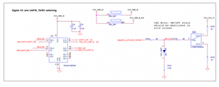
Appreciate the schematic. Think most things look good, but wanted to make sure you are using the correct input voltages for your application.
The TMUX6136 is a dual supply (min +/-5V) or single supply (min 10V) part. Your schematic does not specify what your VCC voltage is, so wanted to make sure you are intending to put between 10V and 16.5V on the VCC pin as you are using it in single supply mode (VSS=GND). In addition, your input to the SEL1/SEL2 pin will be around 2.2V given your voltage divider circuit. While this is fine as the VIH for the SEL pins is minimum 2V, just make sure you are aware of your logic level and the operation of the SEL pins on this device.
I just want to confirm if SEL1 and SEL2 operation is independent of each other, because I want SEL1 to be as input and S1A and S1B as output. SEL2 will be as output and S2A and S2B as input.
Is is possible to work in the above scenario? As per datasheet this IC is a bidirectional IC.
Both SEL1 and SEL2 operate independently. You can toggle each control input independently as long as you have enough control signals to manipulate them like that (in this case you will need another signal to control both individually).
The switch is bidirectional, so the D pins can be configured as an input or output and the S pins can be configured as inputs or outputs as well.