This thread has been locked.

If you have a related question, please click the "Ask a related question" button in the top right corner. The newly created question will be automatically linked to this question.

TS3A4751: Bandwidth for TS3A4751

Part Number: TS3A4751
Other Parts Discussed in Thread: SN74LVC126A

Dear Sir/Madam,

The bandwidth indicated in datasheet for TS3A4751 is 123MHz.

But it didn't mention whether it is at -3dB ?

However there is BW graph in datasheet shown below that at -3dB, the freq is about 70MHz.

Why the info is not tally ?

Thanks.

  • The graph does not mention many test conditions.

    Anyway, typical charcteristics are not guaranteed; if you're asking which number to believe, the answer is "neither".

  • Lee,

    Most of the switch datasheets report in the electrical specifications table the -3dB point below the insertion loss of the switch which could be an additional -0.1-0.5 dB depending on the switch. So you could also think of it as the ~-3.1dB point bandwidth from input to output.

    What did you like about the TS3A4751 that you were going to use this switch and why is the bandwidth important? Maybe we can point you to a different device?

    Thank you,
    Adam
  • Hi Adam,

    I am looking for a switch which can carry 25MHz signal.
    TS3A4751 has been chosen because it has 4 channel , SPST configuration & BW = 123MHz.
    But I still doubt whether this switch can work properly with 25MHz signal without affecting signal integrity.
    After further check on datasheet, the BW shown in the graph is very much difference from it stated in the table.
    I really don't which one should refer to, pls help to advice.
    Thanks.
  • What kind of signal, analog or digital? In the latter case, do you need a specific maximum delay?
  • digital signal & no specific max delay
  • For a unidirectional digital signal, you do not actually need an analog switch that tries to preserve the original voltage level; you can simply use a logic buffer that outputs the same digital state seen at its input.

    The logic equivalent of a unidirectional SPST switch with an active-high control signal is 74xx126. For VCC between 1.8 V and 3.3 V, use the LVC family, e.g., SN74LVC126A.
  • The signal is digital bidirectional & used 1.8V.
  • What is my concern is Bandwidth whether TS3A4751 can be used ?
    Thanks
  • Okay, a simple buffer does not work for a bidirectional signal.

    The 125 MHz bandwith specification is for the - 3 dB point, and was measured in a 50 Ω system. The graph obviously used some different input or output impedance (but keeps it a secret).

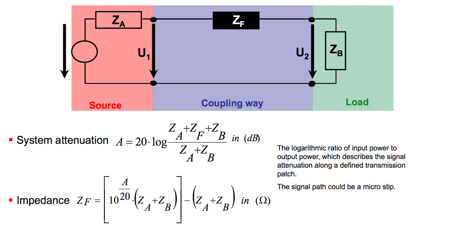
    Your own circuit certainly does not use 50 Ω. If you know your input/output impedances, you can calculate the bandwidth in your circuit:

  • Thanks your explanation.
    What are the advantages of using buffer instead of switch if the source is unidirectional signal ?
    Does it subject to losses due to impedance mismatch ?
    Does it have Ron which would affect signal integrity ?
    How about propagation delay, which one is better ?
    If couple of buffers are put in between, will it cause any ringing, overshoot or other noise ?
  • A logic buffer does not directly pass through the original signal, but generates a new signal that has the same logic state as the input. This means that you can improve on the original signal, e.g., by having faster edges or more drive strength.

    It does not make sense to speak about losses or Ron.

    A buffer has a higher propagation delay than a bus switch, but it's still only a few nanoseconds (depending on the logic family).

    Buffers have a very low output impedance, so it's possible to get ringing if the distances are large enough that you have transmission line effects. This can be prevented by terminating the line properly.
  • How to terminate properly for ringing prevention ?
    If the signal go through two or three buffer, the ringing will be worst than just go through a single buffer?
    What is the BW for SN74LVC126A, will it be reduced along the propagation due to trace length or other factors ?
    Thanks
  • "Bandwidth" is an analog specification; digital buffers have a maximum frequency.

    A buffer decouples its output from its input, so it tends to improve the signal.

    Ringing is a problem only if it is larger than the noise margin and causes the receiver to detect the wrong logic level.

    For possible termination mechanisms, see the AHC or LVC application notes (SCAA034, SCBA010).