This thread has been locked.

If you have a related question, please click the "Ask a related question" button in the top right corner. The newly created question will be automatically linked to this question.

CD74HC4051: worst case leakage current

Part Number: CD74HC4051

My customer is using CD74HC4051M96 in one of their projects and want to know the worst case leakage current for each channel IN/OUT(A0-A7) when Switch is off.

Here are my questions after reading the datasheet.

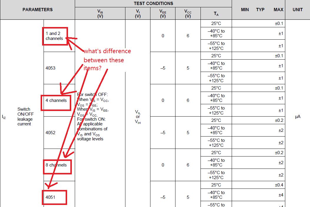
1, when Enable device using Enable pin while switch is OFF for some channels, what’s the difference between 1,2,4 channel, and 4051? Pls view the capture picture as below. Customer wants to know the worst case leakage current for each channel in such condition.

2, when using the Enable pin(pin 6 of 4051) to disable the device, They want to know the leakage current for each channel in worst case.

  • Shashank,

    The SCHS122L datasheet applies to several different parts.  The table you highlighted below contains leakage information for the 4051 (8-channel device) as well as the 4052 (4-channel device) and 4053 (2-channel device). 


    To find the worst case leakage for the SN74HC4051 8-channel device you need to look at the highlighted section below.  The highlighted section contains two leakage measurements under two different test conditions varying VEE and VCC.  The SN74HC4051 max leakage current will be under the test condition with VEE = -5 V and VCC = 5 V because this test places a larger voltage difference on the common input pin which causes more current to leak through the part.     

    The leakage current also varies with temperature.  The worst case leakage will occur at the max temperature 125 deg C. 


    Thank you,

    Adam