This thread has been locked.

If you have a related question, please click the "Ask a related question" button in the top right corner. The newly created question will be automatically linked to this question.

TS3A4751: Issue with TS3A4751RUCR Switch

Part Number: TS3A4751

Hi 

 we are using TS3A4751RUCR in one of our designs. 

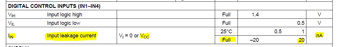
The "In1 to In4" inputs are connected together and pulled down with 20K resistor and controlled by a GPIO of uC. we observe an issue when the Controller tries to enable (pulling the IN inputs to 1.8v) and  the switch  is not functioning as intended. The schematics is attached herewith or your reference. The drive strength of microcontroller is 2mA to 12mA. 

1. what is the input capacitance / load capacitance of "In" inputs?. we couldn't find the details in the datasheet. 

2. can the In1 to In4 be connected together and if connected together what is the drive current required by the "driver" (microcontroller)?

3. Do we need to improve anything on the attached schematics?

Best Regards,

Siva

  • Siva,

    Would you please reattach your schematic it didn't come through? 

    What is the intended function vs what you are observing?  Do you have any scope capture of the IN, COM, NO, and Supply Pins?

    How many boards are you seeing this behavior out of how many built?  Does replacing the device solve the issue? 

    The leakage current spec on the in pin shows that placing a voltage up to Vcc will only have 20nA current leak into the node so you know that your driver is strong enough to toggle this device.

      Thank you,

    Adam

  • Hi Adam,

     thanks for the response. i have reattached the switch schematics in pdf format. Switch_Schematics.pdf 

    we are using this switch to isolate the power rails of two sections of the design. we have a ARM based controller and FPGA in the design. As per the requirements, the ARM controller powers up first and later powers on the FPGA circuits.The power rails for the FPGA circuit goes through the switch. The switch enable inputs "IN1 to 4" are controlled by the ARM controller.  once the ARM powers up and booted, it turns on the switch by "driving 1" and FPGA circuit gets the power. 

    We have manufactured around 18 boards (two different revisions with circuits) and all the boards exhibited the same behavior. replacement didn't solve the issue.


    I do not have the waveforms currently. We will take it and share it across in a day..

  • Siva,

    Thank you for re sending the schematic.  I didn't see any obvious issues upon first inspection.  

    Thank you for explaining the intended operation of the circuit.  

    What is the issue?  What is happening that is not expected?

    With supply voltage at 3.3 V the Vih min is 1.4 V.  Placing a voltage > 1.4V on the IN pin should create a low impedance path between COM and NO to deliver the power to your circuit.

    Thank you,

    Adam

  • Siva,

    Do you have any update to your situation? Do you have any more details of what is happening that is not expected?

    Thank you,
    Adam
  • Siva,

    I haven't heard from you in a couple days so I will assume you have solved your issue. I will close this thread. If you have additional questions you may reply here to reopen it or create a one.

    Thank you,
    Adam