This thread has been locked.

If you have a related question, please click the "Ask a related question" button in the top right corner. The newly created question will be automatically linked to this question.

TMUX1208: Question about TMUX1208 application paired with INA333

Part Number: TMUX1208

Hi team,

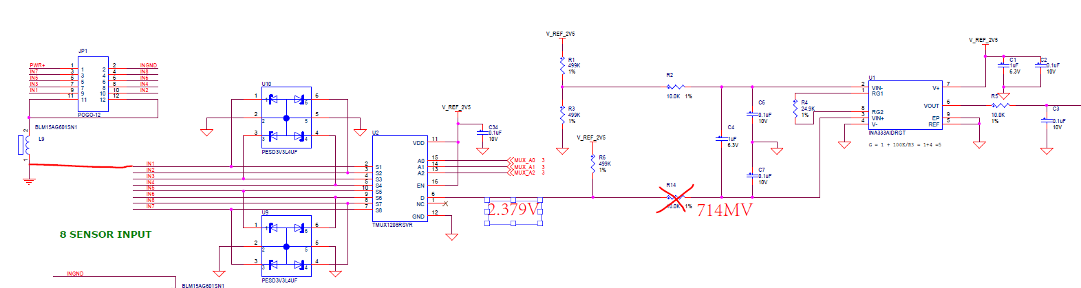
     My customer would like to use TMUX1208 to select sensor input and the output is pulled up with 2.5V supply. When power up with A2,A1,A0=GND and input is 0V, the output would be 2.379V. is there any wrong for the application? Thanks a lot!

Best Regards

Zhengquan Lu

  • Hi Zhengquan,

    Do you have any scope shots from various probe points in the system?

    If the TMUX1208 has A2, A1, A0 =GND then channel S1 is selected. Have you confirmed you have a low resistance path between S1 and D pins? 

    What is your sensor impedance, and output voltage? Scope shots will help explain what you are seeing in the system.

    Additionally, if you capture the same test with the TMUX1208 removed from the system, what do you get at the output?

  • Hi Dakotah,

        Thanks for your reply! For the test, the input is connected with GND, so the output should be also 0V when S1 is selected. Is the schematic diagram is correct? like EN pin connect with 2.5V supply, output pulled up with 2.5V, etc. Thanks a lot!

    Best Regards

    Zhengquan Lu

  • Hi Zhengquan,

    Yes it is okay to have the EN pin tied to VDD at 2.5V. This will ensure the device is enabled.

    Since this is a pass-fet device the voltage is controlled by the rest of the system. If the input signal is 0V, and that channel is connected - then you you should see 0V at the output if it is not being driven by some other source.

    I would recommend disconnecting the output from any other voltage source and measuring the signal. Also probing the sensor output that you believe to be 0V.