This thread has been locked.

If you have a related question, please click the "Ask a related question" button in the top right corner. The newly created question will be automatically linked to this question.

TS5A3359: Isolation in Power-Dowm Mode

Part Number: TS5A3359

Dear TI Experts,

I am wondering about the data sheet of the TS5A3359.

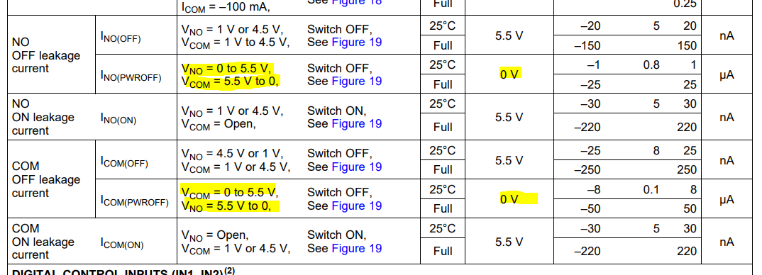
On the one hand, the TS5A3359 features "Isolation in Power-Down Mode". This is explained as follows (Chapter 8.3 page 22):

"When power is not supplied to the VCC pin, VCC = 0 , the signal paths NO and COM are high impedance. This is
specificed in the electrical characterisitics table under the COM and NO OFF leakage current when VCC = 0.
Because the device is high impedance when it is not powered, you may connect other signals to the signal chain
without interference of the TS5A3359."

On the other hand, the allowed voltage range on the analog pins of the mux are restriced to VCC. This is in contradiction to the Power-Down Isolation feature.

Can you please expain this to me?

Regards, Niels

  • Hi, Niels,

    The restriction to VCC is intended for normal operation condition of the device (ie. VCC = 1.65V to 5.5V). The signal passing through should not go above VCC+0.5 in this condition when the device is ON. 

    When the device is OFF (VCC = 0V), the powered-off protection kicks in, and the switch channels are kept in high-impedance mode and voltage up to 5.5V is blocked from the input to the output. In fact, the INO(PWROFF) and ICOM (PWROFF) specs are tested in this condition. 

    For more information on the powered-off protection feature, please refer to the below E2E thread. 

  • Hi David,

    thank you for the information.

    For luck, I have a PCB at hand with the TS5A3359 that I can use for testing.

    I observed that while VCC is 0V, there is isolation as the COM pin stays low despite the fact that NO1 is connected to 3.3V.

    But when VCC rises, as every supply voltage does when it is turned on, I see the COM pin doing mad things as soon as VCC reaches app. 1.4V. This stops when VCC passes app. 1.6V.

    Can you please give me more information about the desired behaviour of the TS5A3359 when leaving the "power off isolation" condition?

    Thanks in advance,
    Niels

  • Hi David,

    here are scope pictures from my TS5A3359 test, I named the signals in the scope-shot according to the TS5A3359 pins:

    Zoom:

    NO2 is connected to ground.
    IN1 and IN2 have pullups to VCC.

    As you can see, COM is isolated from the NOx pins as long as VCC is 0V.
    But when VCC is turned on, the COM pin shows an undesired behaviour during the transition of VCC from 0V to 5V.
    Have a look at NO1. It is driven by a 3.3V, 5A power supply, but you see dips on it while VCC of the TS5A3359 is in the range of 1.4V to 1.6V.

    Do you have an explanation?
    For me, it looks like the TS5A3359 misses isolation while leaving the power-off condition. But I hope I am wrong and you can give me a hint how to avoid the junk at the COM pin.

    I am looking forward to your answer.

    Regards, Niels

  • Hi, Niels,

    The powered-off protection, unfortunately, only applies when VCC= 0V on the TS5A3359. This is why we only spec IOFF leakage current at that specific condition (VCC = 0V).

    The device will start doing some funky things when VCC starts ramping up before it hits the normal operating region. It's not easy to explain but it's basically a result of leakage current from the I/O injected into the switch driver, causing the switch to turn-on slightly (regardless of the logic control status). 

    We improve the powered-off protection design in newly released devices like the TMUX1574 such that the switch remains isolated if the logic control is configured correctly (ex: /EN stays high) when VCC powers up from 0V. 

    Thanks,
    David

  • David,

    thank you for your honest answer.
    It would be great if TI would have enough courage to clearly address such "features" in the datasheet.

    This means that the device is not usable for our application. Sad, but true.

    I wonder if there is any application for such "incomplete" power-off isolation. But that would be a different discussion.

    Regards, Niels

  • Hi, Niels,

    The only goal of the last generation of the "powered-off protection" feature was to keep switches in isolation when the system is powered-off. It was not designed to handle a ramping power supply. 

    We do understand there is such a need in a lot of applications, and that's why we are improving the feature in our new releases. 

    Thank you for your honest feedback!

    Regards,
    David